Phasor

The Phasor is a 12 voice sound card for the Apple II, II plus, IIe and IIGS. Originally designed by Applied Engineering (aka - AE).
The Phasor is usually seen as one Mockingboard by programs which support the Mockingboard. Some programs can even see the Phasor as two Mockingboards, which allow for all 12 voices to be used. Other programs will directly support the Phasor, however the list is much smaller than those that support the Mockingboard.
In 2016 Tom Arnold worked with ReActiveMicro to reproduce a clone of the board called "FAZOR" v1.0beta. On June 6th, 2019 ReActiveMicro released their own v1.0 Phasor expansion card. This is what is currently offered for sale.
WIKI Info: Phasor
Product Status: Actively sold by ReActiveMicro.
Support: Post on the Discussion page (link above) or email ReActiveMicro Support.
Sales: Visit the ReActiveMicro Store.
Future Developments: RM is actively working on v2 which will use custom logic to emulate the ICs.
Kit Assembly
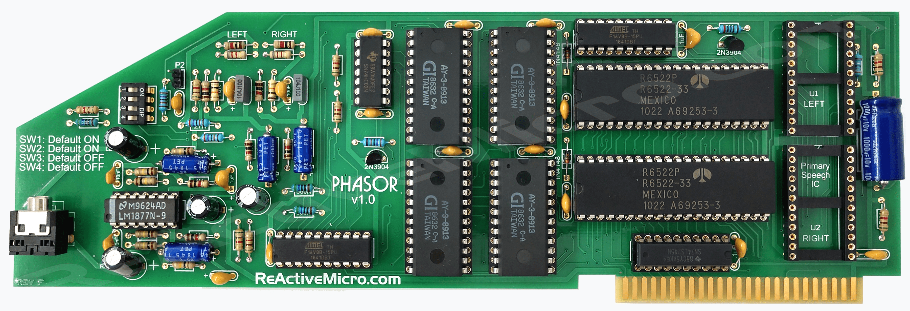
The Phasor Sound Card Kit is a total of 465 pads or "solder joints". It takes about 1 hour or less to fully assemble a kit if you have a decent iron, flux, and solder. The parts included with your kit and the PCB have basic labels. Those with even basic knowledge should have little trouble assembling the kit from the labels on the parts, the bags, and the PCB. The images here of the assembled card can also be used for reference or to determine orientation, such as the diodes.
To assemble your kit we recommend adding parts in groups and then soldering them. This will be the fastest way to assemble the kit rather than adding one part at a time then soldering it.
- Start with the small passive parts like caps and resistors. Some of the location labels will be hard to see if you start with the sockets or other parts. Each time a part is added you can simply bend over a leg on each side to help hold the part to the PCB which allows the board to be turned over and prevents parts from falling out. It is most simple to load all the parts in groups and then solder and clip the legs as needed.
- Once the passive parts are installed next should be the IC sockets. When a socket is loaded on the board bending the corner pins of the sockets helps hole it to the PCB which allows group loading and soldering. The sockets are all the same thickness. So if you solder on a flat surface then this will also help hold all the sockets flat to the PCB and give a more uniform appearance when completed. Be sure ALL pin 1 'notches' are facing the correct way! See the silk screen markings on the PCB to ensure the correct orientation.
- End with the larger parts, like jacks, the large cap, and the header pins. Don't bend over the jack legs or pin legs as they will be too stiff. The jack's legs are prebent also which should help hold it to the PCB. The rest you may need to hold the parts in place as you solder a few pins before you can group solder.
On April 10th, 2021 Alexander Jacocks posted a build video of the Phasor v1.0 Apple II Sound Card Kit. He goes in to some detail about the card, and reviews the PCB and shows the full assembly. About an hour later he has an assembled and working board.
On August 16th, 2020 Old Computer Fun! posted a build video of the Phasor v1.0 Apple II Sound Card Kit. At 10:26 he points out a potential pitfall with cap. Well worth noting.
On April 24th, 2020 Chris Torrence posted a build video of the Phasor v1.0 Apple II Sound Card Kit. He even shows one of the possible mistakes (LS245 backwards). A good vid to review before building your kit! We highly recommend watching it before starting your kit as well as fully reviewing this Wiki page.
Note: A good loupe (magnifying glass) is recommended for helping identify and confirm parts, like the markings on some small caps. It also helps with solder joint inspection. An illuminated 40 x 25mm and a 35 x 50mm loupe are well worth the investment and can be had for about $10 each on eBay.
Some care needs to be taken when installing capacitors and diodes.
If your kit includes Aluminum or Tantalum capacitors, or "caps" for short, then be sure to install them in the correct orientation. The PCB will be clearly marked with "+" signs for all cap locations when the orientation of the part matters, or a polarized part is normally used. Sometimes a non-polarized part is used in place of a polarized one and then its orientation does not matter. However install a polarized cap backwards and you will damage it. An Aluminum Electrolytic will have a strip pointing to the NEGATIVE end lead. A Tantalum Electrolytic will generally have a marking or stripe to denote (not always pointing to) the POSITIVE lead.
- Install the 10uF Aluminum caps at locations C17 and C27. Be sure to install correctly as they are polarized.
All caps will have value markings on them. "106" is 10uF, and "104" is .1uF. 10uF is also typically physically larger than .1uF. This should help identify the ceramic caps in the kit. They along with the Electrolytic caps can also clearly be seen in the assembled pic above.
- Install a 47pF cap at location "C3 (COLOR TRIM)". This can be from any of the two pads on the right to the one pad on the left.
A diode also has a marking on it, and needs to be installed correctly as it only allows current to flow in one direction. Install it backwards and you won't usually damage it, however the circuit will no longer operate as intended. They can also clearly be seen in the assembled pic above.
- Install the diode at location CR1. Be sure to install with the line side down (towards the "A" row).
Show below are example illustrations of different caps, a diode, and their related markings.
-
 Caps Markings
 -
 Diode Markings


Your kit also includes resistors. They should be the less precise "4 band" style which are typically 5% tolerance. You can also use the more precise "5 band" style which are typically 1% tolerance. Here are some charts on how to read them to help make matching locations on your PCB more easy.
-
 4-band Resistor Markings
 -
 5-band Resistor Markings


Software Titles That Support Sound and Speech
We will likely add a table here to better outline all the known titles. However, for now it is best to reference this site: http://www.applevault.com/hardware/sweet_micro_systems/mockingboard/
History
The Phasor was the second project collaboration between Tom Arnold of philosophyofsound.com and Henry from ReActiveMicro. After a bit of market research there seemed be enough demand to warrant this project. Previously Tom had worked on and released a clone of the Mockingboard. This project however would be more difficult since the Phasor uses two PAL devices.
About mid-February 2013 Henry sent Tom a Phasor to depopulate and start the cloning process as Henry was planning to be busy with other non-Apple II related business till about 2014. Tom produced a schematic and then relaid out a new PCB for alpha testing. This would allow testing of the schematic and new components.
Tom worked with the project in his spare time during 2013 and 2014. There was no major rush in the project since Ultimate-Micro still had stock of the Mockingboard v1a they were selling. Not much was done with the project till about mid-2015, after the Mockingboard v1a stock was liquidated.
During the whole process Tom had been trying to copy the protected PAL devices. After several weeks Tom managed to produce a good copy of "PH1". "PH2" however proved to be a lot harder to copy. Henry sent the PH2 device to JammArcade.net who specializes in duplicating older PAL devices. After several weeks they managed to produce a working copy about the very end of 2015.
From 2016 till 2019 Tom Arnold didn't produce any more Phasors. Henry decided to have more units produced with the main goal of also supplying kits. On April 4th 2019 Henry started working on the Phasor v1.0 project. He scanned the PCB, produced new CAD files, and revised the component layout and BOM. The main changes to the project compared to AE was to remove the old RCA audio jacks and use a more common 3.5mm jack, and to remove the thumbwheel potentiometers which set the output volume. The output volume is now hardset at a suitable level for use with amplified speakers most commonly found with desktop PCs.
Phasor Versions
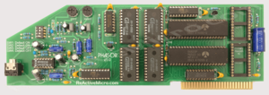
Applied Engineering released the original Phasor in 1984, and it's believed all these early boards are marked "Rev. E" and are missing the 74LS245 near the card's edge connector. This "Rev. F" is from about 1986 and has the 74LS245. It's believed the change was due to a possible issue with the newer IIGS. From a design standpoint it should have been on the card to begin with to comply with Apple's specs as it drives the data bus.
-
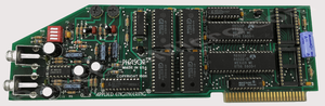 Applied Engineering Phasor.

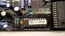
At the very end of June 2016 Tom sent ReActiveMicro a working Fazor v1.0 Beta clone for testing and to include in their raffle at KFEST 2016.
-
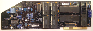 Fazor v1.0 Beta from ReActiveMicro.

-
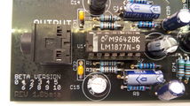 The front "beta" marking on the Fazor.
 -
 The "ReActiveMicro" marking on the Fazor.
 -
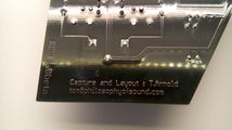 The rear "beta" and "Tom" markings on the Fazor.


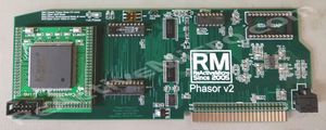
The Phasor v1.0 is the current release of the project. Three exact 1-to-1 sample boards were produced to prove the CAD files and Bill of Materials was correct and factory assembly wasn't an issue. After that the pots were removed and resistors added to set the output volume level. Also removed were the RCA connectors and a more common 3.5mm audio jack was installed. This allows standard desktop speakers to be used.
- Phasor v1.0.x From ReActiveMicro
-
 The Phasor v1.0.0.
Only three with audio pots were produced. -
 The Phasor v1.0.1.
The audio pots were replaced with resistors.


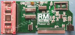
This is the proto project for v2 of the project. It will be based on an FPGA and allow the board to be produced more cheaply when the 6522 and AY-3-8913 ICs become more scarce. However it probably won't be able to be offered in kit form.
- The Phasor v2 Alpha PCB
-
 First Alpha Design
 -
 Second Alpha Design


Reviews & Examples
Here is a good example of the Phasor in use playing the music for the game Nox Archaist.
On April 24th, 2020 Chris Torrence posted a build video of the Phasor v1.0 Apple II Sound Card Kit. He shows how simple and fun this kit can be, as well as a finished product. He even shows one of the possible mistakes (LS245 backwards). A good vid to review before building your kit!
On June 6th, 2019 Chris Torrence posted a review about the Phasor v1.0 Apple II Sound Card. He shows it working with several different programs, and discusses the features and benefit verses the Mockingboard.
ICs Of The Phasor
The main control of the AY-3-8913 Sound Generator ICs is controlled by the 6522 Versatile Interface Adapter (VIA). The Apple II sends commands to the VIAs and the VIAs are connected in a way to send packages of instructions to the Programmable Sound Generators (PSG), and the PSGs produce audio.
The Apple II clock is phase shifted by 180 degrees on the Phasor using an RC Network and a 74HCT02. Part of the Apple II Audio Input circuit is also routed through the 74HCT02.
The SSI-263AP Speech Synthesis IC is not controlled by the VIAs, but is controlled by the onboard GALs. The GALs also produce clock for the PSGs and help control the VIAs.
FPGA Emulation Of Analog ICs
At the heart of the Phasor v2 sound card project is the emulation of the 6522 VIA's and AY-3-8913 Sound Generator ICs.
The FPGA reproduces audio using the same techniques as the Sound Generators. The Digital to Analog Converter (DAC) takes the commands from the 6522 part of the code and modulates the output accordingly. Pulse Width Modulation (PWM) is responsible for mixing and levels. The audio produced is very close to analog. The only real difference is the analog parts of the AY-3-8913 Sound Generator are never the same from IC to IC whereas they are always the same from FPGA to FPGA. The analog audio from the Sound Generators tends to be more "warm" however the audio from the FPGA tends to be more clear. Some high tones tend to be lower or washed out in analog when compared to digital samples. This could also be related to poor design of the filter circuits on the original AE Phasor.
OpAmp And Audio Mixer Circuit
The mixer circuits on the original AE Phasor were not of the best design. Radio Frequency Interference (RFI) and other related noise, channel bleed, and voltage level issues can all be heard on the original card. The Analog and Digital ground separation is also not of the best design. All of these issues were addressed on the ReActiveMicro project.
RFI tends to be heard with CPU, bus, and drive operation and can sound like clicks or slight beeps of varying tones. It's mostly heard when there is no or low audio and the volume is turned up or headphones are used. Channel bleed can be hard when audio is being played in one channel and silence in the other, and can make audio sound more mono or distorted in some cases. Voltage level issues tend to lead to some things sounding louder or softer than others. For example the speech IC tends to sound louder than sound effects or music.
In the Phasor v2 project the second speech IC option was removed since it was unused by all programs and even the test program. There was no known way to test it, although now mb-audit exists (see below) which includes tests for both SSI263 chips. In the current Phasor project the right and left channels for speech are combined for mono output which sounds a lot better than the original signal channel, and the voltage level was normalized to better match the audio output.
Downloadable Files
This is the original AE Phasor test software. It is very limited in what it tests, and due to these limits development of the Phasor v2 project has been delayed. It has been very difficult to find and fix issues as a result. Most of the test software project is actually very simple as the code exists in all the original test programs. Now mb-audit exists (see below) which contains many Phasor-specific tests.
- SERVER FILES
-
 Software
 -
Assorted Files
-
Test files - Tom Porter
- PRINTABLE DOCUMENTS
-
 Programming The Phasor: Part 1
 -
Programming The Phasor: Part 2
-
Manual v1.4 2024
Tom Charlesworth's MB-Audit project: https://github.com/tomcw/mb-audit
This project (released as an Apple II disk image) includes a suit of diagnostic tests that exercise real Mockingboard (and Phasor) hardware to identify any faults in all components on the card: 6522s, AY-3-8913s, SC-01 & SSI263s.
It is regularly updated, and the AppleWin emulator is kept in lock-step with these tests too.