Mockingboard

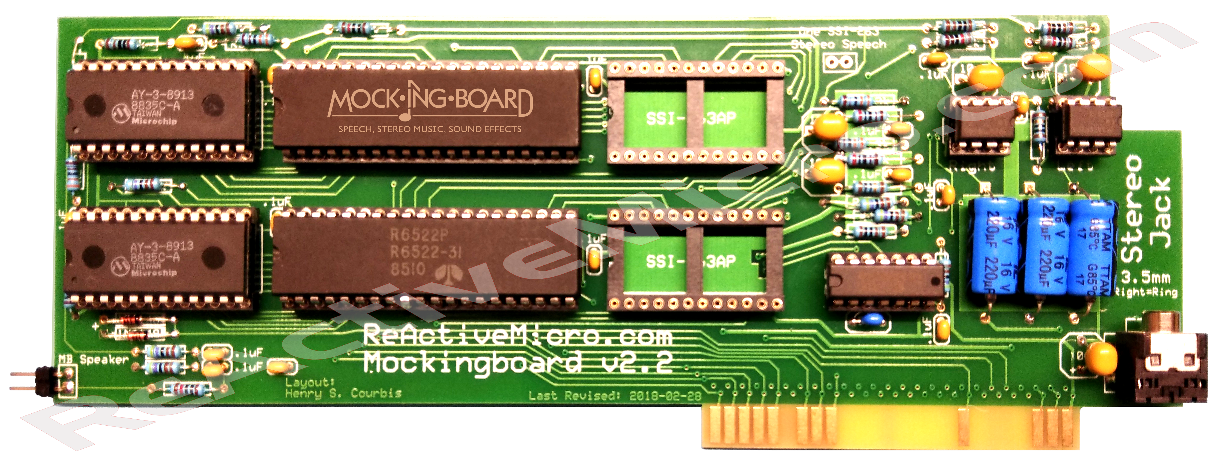
Current version from ReActiveMicro
The Mockingboard is a 6 voice sound card for the Apple II/II plus, IIe, IIGS family of computers. The sound card was originally designed by Sweet Micro Systems. In 2005 ReActiveMicro (then called GSE-Reactive) was the first company to reproduce a clone of the board called "Mockingboard v1.0". Since then ReActiveMicro has released several versions of the Mockingboard in both assembled and kit forms.
Product Status: Actively sold by ReActiveMicro.
Support: Post on the Discussion page (link above) or email ReActiveMicro Support.
Sales: Visit the ReActiveMicro Store.
Installation
Thanks for your support by purchasing your Mockingboard from ReActiveMicro! To install your Mockingboard reference the User's Manual links at the bottom of the page. Generally the board is installed in Slot 4. The 2 Pin Audio Cable can be connected to your Apple II motherboard and to the 2 pin header on the lower left of the Mockingboard labeled "MB Speaker". When you reboot or power on the Apple II you should hear the "beep" over your speakers. If you do not, reverse the 2 pin cable and try again. The sound is only able to transfer with the cable connected one way.
For the Apple IIGS be sure to set your system on "Normal" speed in the Control Panel or the board will not work correctly.
Speech Chip option: The top socket is the primary socket when installing the chip. It is generally labeled SC-02, Arctic-02, SSI-263P, SSI-263AP, or 78A263A-P. The jumper on the "Stereo Speech" 2 pin header allows speech output to both speakers if a Speech Chip is installed. Removing the jumper sends speech only to one speaker.
Kit Assembly
The parts included with your v2.2 kit and the PCB have basic labels. There are 315 pads which need to be soldered. Those with intermediate knowledge should have little trouble assembling the kit from just these labels. The images of the Mockingboard can also be used for reference or determine orientation, such as the diodes.
-
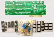
 v2.1 of The Mockingboard Kit.

Note: Some care needs to be taken when installing capacitors and diodes.
If your kit includes Aluminum or Tantalum capacitors, or "caps" for short, then be sure to install them in the correct orientation. The PCB will be clearly marked with "+" signs for all cap locations when the orientation of the part matters, or a polarized part is normally used. Sometimes a non-polarized part is used in place of a polarized one and then its orientation does not matter. However install a polarized cap backwards and you will damage it. An Aluminum Electrolytic will have a strip pointing to the NEGATIVE end lead. A Tantalum Electrolytic will generally have a marking or stripe to denote (not always pointing to) the POSITIVE lead.
All caps will have value markings on them. "106" is 10uF, and "104" is .1uF. 10uF is also physically a lot larger than .1uF. This should help identify the two ceramic caps in the kit. They along with the Electrolytic caps can also clearly be seen in the assembled pic above.
A diode also has a marking on it, and needs to be installed correctly as it only allows current to flow in one direction. Install it backwards and you won't usually damage it, however the circuit will no longer operate as intended. They can also clearly be seen in the assembled pic above.
Show below are example illustrations of different caps, a diode, and their related markings.
-
 Caps Markings
 -
 Diode Markings


Your kit may include resistors. If so they could be the less precise "4 band" style which are typically 5% tolerance. Or the more precise "4 band" style which are typically 1% tolerance. Here are some charts on how to read them to help make matching locations on your PCB more easy.
-
 4-band Resistor Markings
 -
 5-band Resistor Markings


The "MB Sound" connection on the card can be connected with a 2 pin cable to the Apple II motherboard. Disconnect the II's speaker and connect the 2 pin cable to the motherboard and Mockingboard. Turn on the Apple II and if you hear the system beep through your speakers then the cable is connected correctly. If no sound is heard then reverse one of the cable connections and reconnect. If still no sound is heard then there is an issue with the cable or Mockingboard.
Here are the assembly instructions for your reference. These are good to use if you want something local or to print out while soldering.
-
 Mockingboard Assembly Guide PDF 2019
On February 8th, 2018 Joe Strosnider made an assembly and review of the Mockingboard v2.1 Kit. He gives some very good feedback and shows his own assembly of the project. The kit is so simple to assemble with some basic knowledge that as Joe states at 59:46 he just dives in without reading this wiki page or the assembly instructions and has little issue completing his work.
On February 20th, 2018 Chris Torrence's Assembly Lines #62 video podcast did a review of the Mockingboard v2.1. He doesn't show full assembly like Joe Strosnider does, but it's still a good video to learn more in depth about the project and parts as well as mods, pics, and testing.
Software Titles That Support Sound and Speech
We will likely add a table here to better outline all the known titles. However, for now it is best to reference this site: http://www.applevault.com/hardware/sweet_micro_systems/mockingboard/
History
The Mockingboard v1 was the first project ReActiveMicro started with in September 2005. After a bit of market research there seemed be enough demand to warrant this project. The board itself also seemed like a good candidate since it was a simple design, 2 layer PCB, and used standard parts which were still easily sourceable.
Henry disassembled the originally produced Mockingboard and noted what all the parts were. Bill was involved with starting the CAD layout, however he wasn't able to finish, so Henry took over and completed the project. Bill also helped with updating the design from an RCA Audio Cable to a 3.5mm Jack. He is also credited with the concept to add the 3.5mm Jack to the rear side of the IIe, which allows a more simple and shorter cable connection. Henry is credited with adding the II speaker input jack circuit to the board.
Notable Mentions
Henry's work on the Mockingboard project is mentioned in "Sophistication and Simplicity. The Life and Times of the Apple II Computer” by Steven Weyhrich. On page 171 Steven writes "In 2005, Henry Courbis of ReactiveMicro.com produced a fully functioning modern clone of the Mockingboard C, called the Mockingboard v1, selling it for $60. Since he was not equipped for large-scale production and had delays in meeting demand for it, another enterprising hacker, Tom Arnold, produced a clone of the clone in 2010, and sold it through the ReactiveMicro website as the Mockingboard v1a."
Steven however got most of this wrong. For starters there is no "large-scale" anything in the Apple II Community anymore, and this includes demand. Henry had 50 PCBs of the Mockingboard v1 produced, assembled most by hand, and sold the rest as kits. They took almost a year to complete selling. Selling 3-4 boards a month was about the average. Henry wanted to start the Phasor clone project after but was delayed due to other business opportunities. Demand started to grow again and in 2010 is when Tom Arnold said he would be making some more boards to help fill the need in the Community.
Versions

In late 2005 ReActiveMicro (then called GSE-Reactive) produced a clone of the board called "Mockingboard v1". ReActiveMicro sold the Mockingboard v1 in fully assembled, or in user-assemblable "kit" form. There were about 50 units produced and sold. The silkscreen shows "GSE-Reactive.com" on the lower front.
- More Pics Of The Mockingboard Project
-
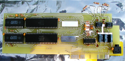 The First Mockingboard v1 Proto
 -
 The Mockingboard v1 in Kit form. From about early 2006.
 -
 The Mockingboard v1 in Kit form. From about early 2006.


In late 2010 Tom Arnold of philosophyofsound.com approached Henry about making a new run of boards. Tom used the ReActiveMicro design but relabeled it as "Mockingboard v1a". About 40 units were produced. The silkscreen shows "ReactiveMicro.com" on the lower front. Ulitmate-Micro helped distribute these boards via the UltimateApple2.com Store. Tom also sold some units himself.

Although still called "Mockingboard v1", in 2015 Tom had another batch of boards made, but this later run has the "UM" logo on it and shows "UltimateApple2.com" and "ReActiveMicro.com" on the lower front. About 30 units were produced.
On October 9th, 2017 Henry relayedout the Mockingboard and incremented the version to v2.1. He also made some mods which is a jumper to allow stereo speech output from a single speech chip. No programs ever used the second speech chip option, so the mod allows better speech output sound. Henry also fixed the reversed channel issue on all previous Mockingboard clones. This version of the board was released for sale as assembled units and kits on January 31st, 2018. v2.0 was released as GERBER files to several people in the Community, however no one ever used the files to make more boards, which prompted the v2.1 "official" ReActiveMicro release.
-
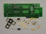
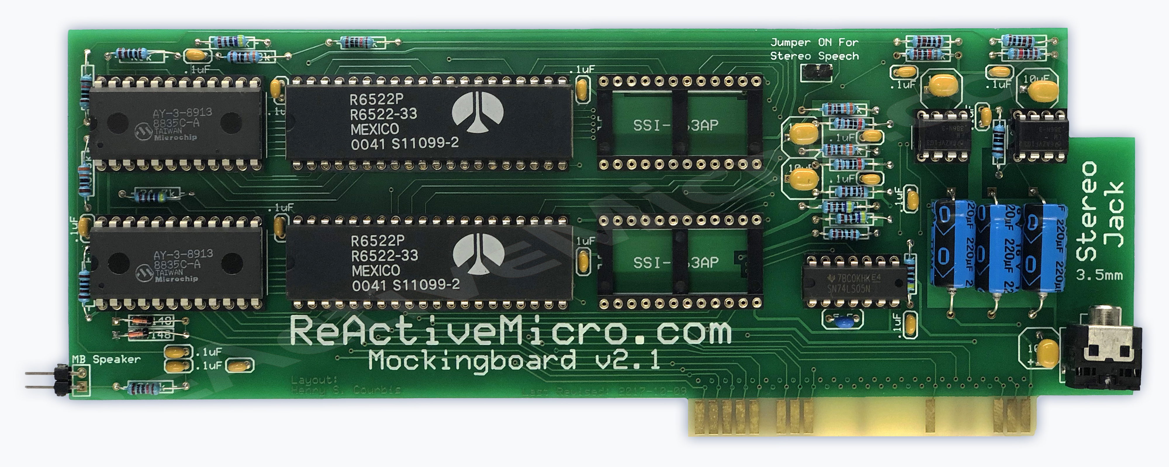
 The Mockingboard v2.1 in Assembled form.
 -
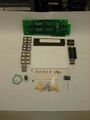
 The Mockingboard v2.1 in Kit form.
On February 28th, 2018 Henry relayedout the Mockingboard and incoremented the version to v2.2. The only change was removal of the stereo speech output jumper. The connection is now defaulted on and made using a trace which can be cut by the user and the header pins and jumper can be added if they wish to reconnect the circuit.
-
 The Mockingboard v2.2 in Assembled form.

Known Design Issues
A few design issues have been discovered over the years in the ReActiveMicro Mockingboards.
On June 15th, 2018 a user reported they receive no sound output from their II motherboard. It seems II, II plus and the Europlus systems are affected. When the sound circuit was being designed no one from the Community was willing to help advise or assist with testing. So there does seem to be an issue affecting some early II systems as noted. This will be addressed in future versions of the design.
In 2016 Chris Torrence discovered that the 3.5mm Audio Jack was wired backwards. This is evident all the way back to the GarberStreet schematic (upper right schematic area, linked below) of the Mockingboard from 2004. v2.1 fixed this issue. Tom Arnold has since devised a work-around mod that Chris demonstrates in a video. In all the years of the Mockingboard being sold no one noticed this issue until Chris did.
All ReActiveMicro Mockingboards up to v2.1 have a cross-channel audio issue as part of the Apple II speaker input circuit Henry designed in 2005. The issue is left and right Mockingboard audio channels get mixed together and can not be distinguished very clearly. Chris also demonstrates this fix in a video. Again, in all the years of the Mockingboard being sold no one noticed this issue until Chris did. v2.2 has this fix standard.
Chris Torrence has a few Assembly Lines videos that can be found on YouTube addressing the different issues listed above. He has been a big help in improving the Mockingboard design and helping the Community, and ReActiveMicro for one thanks him for his time and efforts.
Also noteworthy, but which does not affect ReActiveMicro designs, is a known "Reset Bug" with some early slot-based Mockingboard designs as originally documented by Michael J. Mahon in CALL-A.P.P.L.E. (12/1983). There is a chance the AY Sound Generators will be "stuck" on and producing sound when a program crashes or the Apple II is reset. This is due to no Apple II system /RESET signal being sent to the AY Sound Generators. To resolve this issue two diodes need to be installed, one on each of the AY Sound Generator's Pin 21, to the Apple II's /RESET line. The diodes will allow reset of the AY Sound Generators without running a special program to do so. The Diodes are of course necessary to prevent a system reset from occurring when software wants to reset just the AY Sound Generators through the VIA's PB2 line. All ReActiveMicro Mockingboards have this fix standard, as does the original Mockingboard C from which the clone design and schematic originates.
Downloadable Files

-
Manual
-
 v1 Test Disk 1/2
 -
v1 Test Disk 2/2
-
 Schematic by Bill Garber
 -
 Schematic by Tom Arnold
 -
 Desktop Wallpaper 4096*2304
 -
 A Folder
 -
D Folder
-
M Folder
-
Sound & Speech I Folder
-
v1 Folder


Tom Charlesworth's MB-Audit project: https://github.com/tomcw/mb-audit
This project (released as an Apple II disk image) includes a suit of diagnostic tests that exercise real Mockingboard (and Phasor) hardware to identify any faults in all components on the card: 6522s, AY-3-8913s, SC-01 & SSI263s.
It is regularly updated, and the AppleWin emulator is kept in lock-step with these tests too.