Universal PSU Kit

The Universal PSU Kit is a Power Supply replacement designed by ReActiveMicro to be installed by the end user. It is designed to replace the old Power Supply PCB with a new, modern solution while reusing the old Power Supply Enclosure.
As the name implies, the Kit covers the Apple II, II+, IIe, IIgs, and Apple ///. It was conceived, created, and designed by Henry of ReActiveMicro and released for sale to the Apple II Community on April 25th, 2016. The original Universal PCB bore the "UM" Ultimate-Micro logo till August and technically was a collaborative effort with UltimateApple2.
When do you need a new power supply?
Good question! Although the answer should be obvious. Is it the original, 30+ year old PSU that came with the Apple? Then you need a new one. That simple.
"Rebuild or replace. Don't reuse." - ReActiveMicro.
How much more do you want or expect from a piece of equipment that was only designed to last a few years at most? Do you really believe Apple designed the power supply to last 30+ years? Most people are either unaware of the potential dangers of continuing to use an old PSU or are of the mindset "If it ain't broke, don't fix it." Luckily when most Apple II power supplies fail they don't cause damage, or at least none which is apparent. However there is growing evidence that when some power supplies fail the Apple II system in which they failed start to have intermittent issues a period of time after the failure.
It is highly recommended to fully rebuild your power supply or install a Universal PSU Kit. You should NOT rely on an original power supply in any case, or even one 'only' 10 years old, as it can be unreliable. It is also very hard, if not impossible, to fully test a power supply using common bench top tools. Labs use very expensive and specialized equipment specifically made for testing power supplies to certify and calibrate them. Transcat is one such company which not only calibrates your power supply but also documents how and why it fails certain tests. Costs however can rage in to the upper hundreds of dollars which is why most users decide to replace their power supply with something new and known good, or attempt a rebuild. However without the tools or knowledge to fully test and calibrate a rebuild you're back to just assuming things are working correctly.
Project Status: Complete. In production. Actively sold by ReActiveMicro.
Support: Post on the Discussion page (link above) or email ReActiveMicro Support.
Sales: Visit the ReActiveMicro Store. See the IIe, IIgs, or /// sections for Kits and Cables.
History / Project Revisions
The Universal PSU Kit v1.0 project was released for sale to the Apple II Community on April 25th, 2016. At the date of release ReActiveMicro was still in the process of setting up and testing their new Store and Wiki. The project became a "collaborative" release with UltimateApple2 in order to have Kits available for the initial delivery release at KFEST 2016. After KFEST the rest of the pre-orders were shipped to buyers.
Up until August 2016 the Ultimate-Micro.com Store was the only vendor who distributed the project. Then as part of ReActiveMicro.com's full return from hiatus with their new Store and Website release they took over sales and distribution to better serve and support the Apple II Community. At this time the Universal PCB was also revised with the ReActiveMicro logo.
On May 7th, 2017 ReActiveMicro re-released the Universal PSU Kit as v1.1 at a new lower price and with a new Universal PSU unit. This new Universal PSU is equivalent to the v1.0 unit in all specs. We moved from a SinPro PSU to another manufacturer who is more responsive and is willing to help improve the design for retro platform use.
-
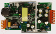 Universal PSU v1.1 (early 2017)
 -
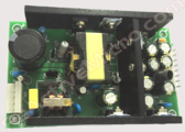 Universal PSU v1.1 (late 2017)


On June 29th, 2018 Henry relaid out the Universal PCB to include support for the Euro enclosure 699-0161-A / AA11042C. Also updated was the Universal PSU, which is equivalent to the v1.0 unit in all specs. A new feature added is a spring connector on the AC side to make installations more simple for the user. Some users reported the MTA connectors to be tedious and hard to terminate the wires in. 50 units were produced, however most were installed within PSU upgrade or the new UA2 Enclosure. Only a few were sold as kits. Also changed was C5 and C6 to 0805 parts on some PSUs for production testing. We found evidence the 1206 parts were susceptible to cold solder joints. We had two choices to address the issue. Change the part's footprint or change the part. So we chose to change the part to the smaller size, which seems to have resolved the issue. The revision for the project was incremented to v1.2 officially.
-
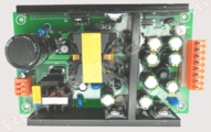 Universal PSU v1.2

On November 6th, 2018 ReActiveMicro re-released the Universal PSU Kit as v1.3 with a new Universal PSU unit design. This new Universal PSU is equivalent to the v1.2 unit in all specs. The new feature is spring connector on the DC side to make installations more simple for the user. We also kept the MTA-156 connector to make installation of custom cables simple. The PWM control resistor (R10) was also changed from 100k to 68.3k. Three users to date reported "coil whine" which we found to be a very inconsistent issue, however to keep the project uniform we changed out the resistor. Efficiently for the PSU is negligibly affected with this change. However now any magnetostriction frequencies are kept outside the range of human hearing. Also notable is now all the connector legends are printed on the PCB to make verifying or connecting wires more simple for the end user.
-
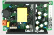 Universal PSU v1.3
 -
 AC Connector
 -
 DC Connectors


Pre Installation Notes
Thanks for your support by purchasing your Universal PSU Kit from ReActiveMicro! To install your Universal PSU Kit you can reference the links on this page which are up to date, or the older Install Guide .PDF at the bottom of the page. Generally the Kit can be installed in about 15 minutes and with only light skimming of the installation section on this page or the Install Guide.
All parts should be included with your Universal PSU Kit. If you find anything missing please contact Support.
Tools Required:Philips Screwdriver, Small Slotted Screwdriver, Slip-Joint Pliers. Optional Tools: Wire Cutters/Strippers, Multimeter.
ALWAYS be sure to disconnect all power from your power supply before opening and upgrading the unit. And be sure to double and triple check the DC output voltages before reconnecting the power supply to your Apple II system. If you connect something wrong you will destroy your Apple II. You have been warned. If you purchased any of our DC Output Cables then you should still recheck the cable is correct, however we always test the cables we sell. Rechecking will never be a bad idea and we always recommend it.
IMPORTANT NOTES: The Universal PSU design has an adjustable Output Voltage Potentiometer. It comes preset from the factory and locked in place with security adhesive. We HIGHLY RECOMMEND not adjusting it under any circumstances as it could cause damage to your Apple II and void your Universal PSU warranty. Only those with knowledge or need should ever adjust. You have been warned. Once the Enclosure has been upgraded to the Universal PSU it MUST be fully mounted in the computer case in order for Ground to be connected to Common on the DC Output. This connection is achieved by the Enclosure mounting screws or case clips.
Kit Installation: Enclosure 606-5001
BEFORE YOU BEGIN BE SURE TO REMOVE THE POWER SUPPLY FROM YOUR APPLE AND DISCONNECT FROM AC.
II/+/e: Remove the mounting screws from the bottom of the Apple case to remove the power supply from chassis.
- To open your Apple II Power Supply Enclosure start by removing the 8 small screws (4 on each side) on the bottom edge of each long side. The bottom panel of the enclosure can then be removed. Be sure not to remove any other screws, or be sure to replace them if you accidently did.
-
- You will find the old PSU PCB mounted to the top of the enclosure with 4 screws in a diamond-shape pattern. Remove these 4 screws. The old PSU PCB should now be loose, however the AC and DC wires are securing it to the case.
-
- Next, remove the 2 AC wires from the old PSU PCB. Some PCBs may have removable Pin style connectors. Most however have soldered wires that need to be cut from the old PCB. If the wires looks like they just end at the old PSU PCB and can’t be removed when gently pulled, then they should be cut as close to the old PSU PCB as possible. Leave the green ground wire connected to the enclosure.
- Removal of the old PSU PCB.
- If you purchased a new DC Output Connection Cable then you will remove the old PSU PCB, DC Output Connection Cable, and grommet from the enclosure as one piece. The grommet can be removed by using pliers and turning it 90-degrees which will unlock it from the enclosure.
- If you didn’t purchase a DC Output Connection Cable then be sure to cut the cable as close as possible from the old PSU PCB and leave it installed in the enclosure.
- Once the old PSU PCB has been removed you can now mount the new Universal PCB.
- For this enclosure be sure to break off the small end of the Universal PCB as noted on it. Lay the Universal PCB on the edge of a counter or desk and while securely holding the main part of the PCB apply pressure to the small end to be broken off. It is surprisingly strong, however it will break cleanly.
- The mounting points on the Universal PCB are clearly marked for this enclosure. Be sure to reuse all mounting screws.
- Next, mount the new Universal PSU to the brass standoffs pre-installed on the Universal PCB with the M3 screws enclosed. The “AC End” has the orange MTA156, 5 Position connector already installed on one side, and the “DC End” has the orange MTA156, 8 Position connector already installed on the other side. Be sure to mount the new Universal PSU correctly.
-
- Connect the AC wires to the Universal PSU.
- The AC wires should easily reach the MTA156, 5 Position connector pre-installed on P1 of the Universal PSU. If the AC wires are too short to reach the MTA156, 5 Position connector and they DO NOT have Pin style connectors then you can use the 18AWG wire from the Male Pin Connectors included with the Kit and the included Splices. Just cut the wire from the Male Pin Connector. The Red Scotchlok Quick Crimp Splice will require pliers.
- If your old enclosure has removable Pin style connectors, then use the Male Pin Connectors to make the connection. Wire the Male Pin Connector tails to connect to the MTA156, 5 Position connector already connected to the Universal PSU.
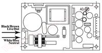
- The Black or Brown wire in the enclosure will be the HOT or the LIVE wire. The White or Blue wire will be Neutral.
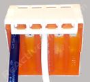
- Using a small slotted screwdriver, push the Black or Brown wire to the MTA156, 5 Position connector in the location closest to the large capacitor near the middle of the PSU PCB (see below for diagram). No need to strip or prep the wire in any way. The MTA156 connector is designed to automatically cut the insulation of the wire and make a permanent connection. Just make sure the wire is fully inserted into the MTA156 connector (see example pictures below). Note: Some AC wires are very thin. We have included an extra MTA156, 5 Position, 20AWG Yellow Connector for use with these smaller AC wires. If in doubt you can try to use the Orange MTA156, 5 Position connector and if you find the Universal PSU won’t turn on then you can redo the AC connections using the Yellow MTA156, 5 Position connector. In contrast, some wires are thicker and will require a little extra work to insert them in to the MTA156, 5 Position connector.
- The other remaining wire goes exactly in the middle of the MTA156, 5 Position connector. Nothing is connected to the other positions. Ground is supplied to the Universal PSU using the frame of the Apple II Enclosure and the mounting screws you already installed in Step 6.
- Install the Strain Relief Cap onto the top of the MTA156 connector.
-
v1.3
-
 v1.0 to 1.2
 -
-
-
- Connect the DC Output Connection Cable.
- If you purchased a new DC Output Connection Cable you can now connect it on the Universal PSU. You can reuse the original grommet if you wish, and there should be one included with the new DC Output Connection Cable if needed. Use pliers to turn the grommet 90 degrees to lock it in place once installed.
- If you are reusing the original DC Output Connection Cable then you need to connect the wires to the MTA156, 8 Position connector already connected to the Universal PSU. As with the AC side MTA156 Connector you will notice it is only possible to connect the wires so they run away from the Universal PSU. So we will call the MTA156 connector position closest to the Power LED “Pin 1” (+12v) for reference (also marked on the bottom PSU PCB).
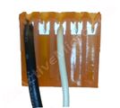
- Strip and push the wires into the Spring connector as show in the picture. Or for the older MTA156, 8 Position connector using a small slotted screwdriver in the following order:
- Pin 1 (+12v): Yellow (sometimes White with Orange Stripe)
- Pin 2 or 3 (+5v): Orange
- Pin 4 (Ground): Black
- Pin 5 (Ground): Black
- Pin 6 (-12v): Green (sometimes White with Blue Stripe)
- Pin 7 or 8(-5v): Blue
- Now would be a good time to recheck all your connections to make sure they are secure and wired correctly. If you have a multimeter it would be best to perform a “continuity test” on all connections as well. You can also turn on the Universal PSU, with the enclosure open and not connected to your Apple, and use the multimeter to check the output voltages as referenced above. There is a Power LED next to the DC Output Connector which will help aid in confirming AC is correctly connected to the Universal PSU and turned on.
CAUTION: Do not directly touch the Universal PSU or its parts for any reason when AC power is applied as electrical shock can and will occur. Be sure to wait at least 10 seconds after AC power has been disconnected before directly touching. - All that is left is to reassemble the enclosure and connect the DC Output Cable to your Apple motherboard.
- Replace the enclosure screws removed in Step 1.
- Check for any rattling noises coming from the enclosure with some light shaking. If anything is heard be sure to reopen the enclosure to investigate and remove the loose item(s) as they could cause issues or damage during use.
- Done! Enjoy another 10+ years of trouble free, clean DC power in your Apple II/+/e or Clone computer. And rest assured knowing you have made the best decision possible in extending and protecting the life of you Apple.


Kit Installation: Enclosure 699-0161-A / AA11042C
BEFORE YOU BEGIN BE SURE TO REMOVE THE POWER SUPPLY FROM YOUR APPLE AND DISCONNECT FROM AC.
II/+/e: Remove the mounting screws from the bottom of the Apple case to remove the power supply from chassis.
- To open your Apple II Power Supply Enclosure start by removing the small screws on the bottom edge of each long side. The bottom panel of the enclosure can then be removed. Be sure not to remove any other screws, or be sure to replace them if you accidently did.
- You will find the old PSU PCB mounted to the bottom of the enclosure with 4 nuts. Remove these 4 nuts. The old PSU PCB should now be loose, however the AC and DC wires are securing it to the case.
- Next, remove the AC wires from the switch.
- Removal of the old PSU PCB.
- If you purchased a new DC Output Connection Cable then you will remove the old PSU PCB, DC Output Connection Cable, and grommet from the enclosure as one piece. The grommet can be removed by using pliers and turning it 90-degrees which will unlock it from the enclosure.
- If you didn’t purchase a DC Output Connection Cable then be sure to cut the cable as close as possible from the old PSU PCB and leave it installed in the enclosure.
- Once the old PSU PCB has been removed you can now mount the new Universal PCB.
- The mounting points on the Universal PCB are clearly marked for this enclosure. Be sure to reuse all mounting screws. Reinstall all 4 nuts.
- Next, install the C-14 power connector in to the enclosure. Then install the new wires as pictured.
-
- Next, mount the new Universal PSU to the brass standoffs pre-installed on the Universal PCB with the M3 screws enclosed. The “AC End” has the orange MTA156, 5 Position connector already installed on one side, and the “DC End” has the orange MTA156, 8 Position connector already installed on the other side. Be sure to mount the new Universal PSU correctly.
-
- Connect the AC wires to the Universal PSU.
- The AC wires should easily reach the MTA156, 5 Position connector pre-installed on P1 of the Universal PSU.
- Wire the Male Pin Connector tails to connect to the MTA156, 5 Position connector already connected to the Universal PSU. The Black wire in the enclosure will be the HOT or the LIVE wire. The Blue wire will be Neutral.
- Using a small slotted screwdriver, push the Brown wire to the MTA156, 5 Position connector in the slot closest to the large capacitor near the middle of the PSU PCB (see below for diagram). No need to strip or prep the wire in any way. The MTA156 connector is designed to automatically cut the insulation of the wire and make a permanent connection. Just make sure the wire is fully inserted into the MTA156 connector (see example pictures below).
- The Blue wire goes exactly in the middle slot of the MTA156, 5 Position connector.
- The Green wire goes on the end slot of the MTA156, 5 Position connector.
- Install the Strain Relief Cap onto the top of the MTA156 connector.
- Connect the DC Output Connection Cable.
- If you purchased a new DC Output Connection Cable you can now connect it on the Universal PSU. You can reuse the original grommet if you wish, and there should be one included with the new DC Output Connection Cable if needed. Use pliers to turn the grommet 90 degrees to lock it in place once installed.
- If you are reusing the original DC Output Connection Cable then you need to connect the wires to the MTA156, 8 Position connector already connected to the Universal PSU. As with the AC side MTA156 Connector you will notice it is only possible to connect the wires so they run away from the Universal PSU. So we will call the MTA156 connector position closest to the Power LED “Pin 1” (+12v) for reference (also marked on the bottom PSU PCB).
- Strip and push the wires into the Spring connector as show in the picture. Or for the older MTA156, 8 Position connector using a small slotted screwdriver in the following order:
- Pin 1 (+12v): Yellow (sometimes White with Orange Stripe)
- Pin 2 or 3 (+5v): Orange
- Pin 4 (Ground): Black
- Pin 5 (Ground): Black
- Pin 6 (-12v): Green (sometimes White with Blue Stripe)
- Pin 7 or 8(-5v): Blue
-
-
- Now would be a good time to recheck all your connections to make sure they are secure and wired correctly. If you have a multimeter it would be best to perform a “continuity test” on all connections as well. You can also turn on the Universal PSU, with the enclosure open and not connected to your Apple, and use the multimeter to check the output voltages as referenced above. There is a Power LED next to the DC Output Connector which will help aid in confirming AC is correctly connected to the Universal PSU and turned on.
CAUTION: Do not directly touch the Universal PSU or its parts for any reason when AC power is applied as electrical shock can and will occur. Be sure to wait at least 10 seconds after AC power has been disconnected before directly touching. - All that is left is to reassemble the enclosure and connect the DC Output Cable to your Apple motherboard.
- Replace the enclosure screws removed in Step 1.
- Check for any rattling noises coming from the enclosure with some light shaking. If anything is heard be sure to reopen the enclosure to investigate and remove the loose item(s) as they could cause issues or damage during use.
- Done! Enjoy another 10+ years of trouble free, clean DC power in your Apple II/+/e or Clone computer. And rest assured knowing you have made the best decision possible in extending and protecting the life of you Apple.


Kit Installation: Apple ///, Enclosure AA11190
BEFORE YOU BEGIN BE SURE TO REMOVE THE POWER SUPPLY FROM YOUR APPLE AND DISCONNECT FROM AC.
- Turn your Apple /// over. Loosen but don't remove the two small screws next to the Power Switch holding the Power Supply Pan flange down.
-
- Remove the 8 screws securing the Power Supply.
-
- Flip the Power Supply up. You should now be able to remove the DC Output Cable.
-
- Remove the brown wire from the Power Switch, and blue wire from the PCB.
-
- Remove the old PSU PCB.
- You may need to reorient the green/yellow Ground Wire to clear the Universal PCB. Now is a good time to check and rotate the Wire and Connector to a better position. Loosen the Nut, move the Wire, and re-secure the Nut.
-
- You can now mount the new Universal PCB.
- The mounting points on the Universal PCB are clearly marked for this Enclosure. You will only be reusing 6 of the 7 original mounting screws to attach the Universal PCB. Screw the remaining one in to its hole on the Power Supply Pan so that it doesn’t get lost.
- Connect the Female Spade Connector and Wire to the Power Switch. Next connect the Male Pin Connector with Housing and Wire to the blue Wire on the AC Connector.
-
- Next, mount the new Universal PSU to the brass standoffs pre-installed on the Universal PCB with the M3 screws enclosed. The “AC End” has the orange MTA156, 5 Position connector already installed on one side, and the “DC End” has the orange MTA156, 8 Position connector already installed on the other side. Be sure to mount the new Universal PSU correctly.
-
- Connect the AC wires to the Universal PSU.
- The AC wires should easily reach the MTA156, 5 Position connector pre-installed on P1 of the Universal PSU. If the AC wires are too short to reach the MTA156, 5 Position connector and they DO NOT have Pin style connectors then you can use the 18AWG wire from the Male Pin Connectors included with the Kit and the included Splices. Just cut the wire from the Male Pin Connector. The Red Scotchlok Quick Crimp Splice will require pliers.
- If your old enclosure has removable Pin style connectors, then use the Male Pin Connectors to make the connection. Wire the Male Pin Connector tails to connect to the MTA156, 5 Position connector already connected to the Universal PSU.
- The Black or Brown wire in the enclosure will be the HOT or the LIVE wire. The White or Blue wire will be Neutral.
- Using a small slotted screwdriver, push the Black or Brown wire to the MTA156, 5 Position connector in the location closest to the large capacitor near the middle of the PSU PCB (see below for diagram). No need to strip or prep the wire in any way. The MTA156 connector is designed to automatically cut the insulation of the wire and make a permanent connection. Just make sure the wire is fully inserted into the MTA156 connector (see example pictures below). Note: Some AC wires are very thin. We have included an extra MTA156, 5 Position, 20AWG Yellow Connector for use with these smaller AC wires. If in doubt you can try to use the Orange MTA156, 5 Position connector and if you find the Universal PSU won’t turn on then you can redo the AC connections using the Yellow MTA156, 5 Position connector. In contrast, some wires are thicker and will require a little extra work to insert them in to the MTA156, 5 Position connector.
- The other remaining wire goes exactly in the middle of the MTA156, 5 Position connector. Nothing is connected to the other positions. Ground is supplied to the Universal PSU using the frame of the Apple II Enclosure and the mounting screws you already installed in Step 6.
- Install the Strain Relief Cap onto the top of the MTA156 connector.
-
v1.3
-
v1.0 to 1.2
-
-
-
- Connect the DC Output Connection Cable.
- If you purchased a new DC Output Connection Cable you can now connect it on the Universal PSU. Remove the existing MTA156, 8 Position connector already installed to the Universal PSU, then install the new DC Output Connection Cable.
Note: Due to the complexity of the /// DC Output Connection Cable and the ease at which a wiring mistake can be made we HIGHLY RECOMMEND purchasing a new DC Output Connection Cable. - If you are reusing the original DC Output Connection Cable then you need to connect the wires to the MTA156, 8 Position connector already connected to P2 the Universal PSU. As with the AC side MTA156 Connector you will notice it is only possible to connect the wires so they run away from the Universal PSU. So we will call the MTA156 connector position closest to the Power LED “Pin 1” (+12v) for reference (also marked on the bottom PSU PCB).
- Locate the power connector on the Apple /// motherboard. Consider the pin nearest the front of the computer to be pin 1. And the pin nearest the rear of the computer (AC end) to be pin 10. You will see some markings on the motherboard, however they aren't very clear. Here is their pinout:
- Pin 10 = +12
- Pin 9 = +12
- Pin 8 = +5
- Pin 7 = +5
- Pin 6 = -5
- Pin 5 = GND
- Pin 4 = GND
- Pin 3 = GND
- Pin 2 = GND
- Pin 1 = -12
-
DC Side Pinouts
-
 /// Motherboard Power Connector
- Strip and push the wires into the Spring connector as show in the picture. Or the wiring from the /// Motherboard Power Connector to the PSU MTA156, 8 position, DC Output Connector is the following:
/// PSU +12v Pin 10, Pin 9 Pin 1 +5v Pin 8, Pin 7 Pin 2, Pin 3 GND Pin 5, Pin 4, Pin 3, Pin 2 Pin 4, Pin 5 -5v Pin 6 Pin 7 or 8 -12v Pin 1 Pin 6 Note: Install no more than 2 wires per MAT156 connector position.
/// Pin 1 nearest the front of the computer.
PSU Pin 1 nearest the LED. - Install the Strain Relief Cap onto the top of the MTA156 connector.
-
- If you purchased a new DC Output Connection Cable you can now connect it on the Universal PSU. Remove the existing MTA156, 8 Position connector already installed to the Universal PSU, then install the new DC Output Connection Cable.
- Now would be a good time to recheck all your connections to make sure they are secure and wired correctly. If you do not check the voltages AND you inadvertently connect something wrong you will DESTROY your Apple. Be sure to check the wiring and voltages without exception!
- Use a multimeter to perform a “continuity test” on all connections between DC MTA connectors.
- With the enclosure open and not connected to your Apple, turn on the Universal PSU and use a multimeter to check the output voltages as referenced above. There is a Power LED next to the DC Output Connector which will help aid in confirming AC is correctly connected to the Universal PSU and turned on.
- All that is left is to reassemble the Power Supply to the Apple /// and connect the DC Output Cable to your motherboard.
- Replace the screws removed in Step 1 and Step 2.
- Done! Enjoy another 10+ years of trouble free, clean DC power in your Apple /// computer. And rest assured knowing you have made the best decision possible in extending and protecting the life of you Apple.


Features Of The Universal PSU Kit
- Fits all standard Apple II and /// Power Supply Enclosures. (all parts included, user supplies household tools)
- Meets or surpasses all Apple II and /// power requirements.
- Modern PSU design.
- Standard 2 year warranty.
- Universal PSU operates on a wide range of input power: 90-264VAC, 47-63Hz.
- On-board Power LED shows when AC is applied to the Universal PSU and is working.
- Constant Voltage design
- Fast Power Reset: No more “hung” systems or need for long off periods and waiting before turning back on.
- Interchangeable DC Output Cable for II/+/e/gs/III. One PSU can support all!
- Runs cool/low heat output: Operates cooler than the original Apple II PSU.
- Cleaner and more consistent power than the original Apple II PSU.
- More efficient than original Apple PSU: Consumes 1.6A at 100v, 1A at 230v, 63W max at full output: +5v 6A, +12v 3A.
- Fused AC Over Current/Over Voltage/Surge protection.
- DC Over Voltage protection (active crowbar design), and auto restart.
- Fully UL/CE Certified and tested design.
- All units fully stress-tested/burned-in at 90% loading before shipping.
- Kit is “reversible”. You can downgrade your Enclosure back to its original state if desired in the future.
Reviews
On December 28th, 2017 the YouTube channel "Things Humans Do" posted a review of a custom install of the ReActiveMicro Universal Power Supply. It's an install without the full Kit of parts. It's not as simple as the Universal PSU Kit. However it looks to be a lot more fun with his custom approach. A hammer and a cat makes guest appearances as well. Perhaps it's an AppleCat?
On April 24, 2016 Joe Strosnider posted a review of The Universal PSU Kit. He gives some very good feedback and shows an installation on one of his own PSU Enclosures.
On April 24, 2016 Chris Torrence from the YouTube channel "Assembly Lines" posted a review of The Universal PSU Kit. He gives some very good feedback and shows an installation on one of his own PSU Enclosures.
Project Progression: Inception
When Henry from ReActiveMicro first returned to the Apple II he found several systems obtained had Power Supply issues or wouldn't power on. Some systems appeared to work but had very intermittent problems. This caused several issues with testing and projects.
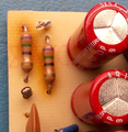
Henry started by diagnosing most issues back to the Power Supply. These units were about 20 years old at the time, and were only designed to last 5 at the most. A lot of the parts responsible for voltage regulation were either dried out or had been over heated. Some capacitors even showed signs of being swollen. Any bulging top means that they are damaged, will not function properly, and should be replaced immediately.
During his research Henry found that all Apple Power Supplies were designed very poorly. Parts were always under sized for the job they were required to do. This led to many parts overheating. Some even get so hot as to discolor the fiberglass PCB (pictured right). Many Power Supplies sampled showed signs of extreme over-stressing. This isn't as much of an issue with lightly loaded systems, however those systems loaded with peripheral cards or high-drain devices may see more apparent issues or even Power Supply failures.
So Henry was faced with two options: Rebuild the 20+ year old Power Supply Unit (PSU), or find a replacement which could be mounted in the Apple II and Apple ///.
- Examples Of Overheated PCBs
-
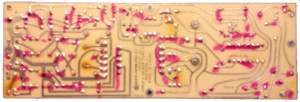 Rear of common PCB damage.
 -
 Front of common PCB damage.


Project Progression: Rebuild
Henry first started by rebuilding old Apple II PSU boards in 2005. This however posed some issues since there were many variations of the PSU boards. Each board has at least 50 parts. Some parts are hard to access and remove. Other parts are so old they are no longer produced and need to be cross referenced with newer parts. And worst of all, most parts are under sized and need to have their ratings increased so they are no longer being over-stressed.
The time involved on a PSU PCB rebuild is in the range of 5 hours. Some of the replacement parts can also be costly and hard to find. The amount of time and effort needed to even rebuild 5 PSUs just didn't seem worth it after a while. A major issue remained however. The heart of the PSU still wasn't being replaced - the Step-down Transformer. This was the one part which is no longer produced. There is some New Old Stock (NOS) to be found, however it is not new and is still 20+ years old.
The problem here is the copper wires inside the Transformer are coated with a very thin insulating coating. After years of oxidation and wear of heating up and cooling down cracks form which leads to the Transformer shorting out and usually lots of smoke and even fire. Worse than this however is it can lead to the Transformer outputting voltages far in excess of what they should be. This is the primary cause of damage to motherboards and peripherals. Parts will be over-stressed due to the unregulated voltages output by a dying Transformer. If this doesn't lead to instant failure of an IC, then it will weaken it which leads to an early demise or intermittent issues. The Transformer doesn't need to fail for such damage to be caused. Many of the regulating Diodes can also fail and cause damage in the same way.
Project Progression: ATX PSU

In 2006 Henry changed his approach from repair to replacement. The new concept would be to remove the old Apple PSU PCB and replace it with a new ATX PSU PCB.
Henry found a U2 size ATX Power Supply (now called Mini ITX) which came standard with the -12v and -5v outputs. Most Power Supplies no longer supply -5v, which the Apple II requires. This "U2" size was however a perfect fit for a replacement PSU PCB option. This approach however had some issues.
First, Henry would need to disassemble the ATX Power Supply and remove the ATX PCB. Next, the bare ATX PCB didn't mount to the Apple II Enclosure's mounting points. Apple's Enclosures don't have any standardized mounting points inside. These mounting points change from model to model. This forced Henry to modify the Apple PSU Enclosure - something he is against. He would need to remove or add standoffs in order to firmly secure the new ATX PCB inside the Enclosure. Lastly, connecting the Apple II DC Output Cable to the ATX PSU proved time consuming. In fact the whole upgrade procedure would take about 2 hours to complete. This coupled with the cost of a Server grade U2 ATX Power Supply proved an expensive option for most users.
After about a year of selling the ATX replacement they were discontinued until a better option could be found.
Project Progression: Universal PSU Kit
In 2015 Henry revised the Power Supply project after experiencing issues in a project that once again turned out to be power related. After some more research Henry learned that ATX was not a good solution for the Apple II. It poses several issues. For example the "IOmin" values are never met, and the +3.3v output is not used. Some ATX PSUs also have a +5v VSB output that isn't used in the Apple II. And most ATX units today don't have -5v anymore, so we are forced to make it.
Not meeting the IOmin values can cause something as simple as reduced power or voltage regulation, or even the ATX PSU not turning on. It can also lead to things a lot worse such as wild swings in output voltages far beyond what is normal and the PSU overheating or burning up. Issues can and will be inconsistent and are affected by temperatures, humidity, how "clean" the AC input power or voltage is, and loads. An ATX PSU is NOT the right choice for an Apple II in ANY situation.
An ATX PSU is not designed to operate with a load as low as the Apple II. The Apple II only requires about 15w of power. It's like a Buggy: Dependable, easy to repair, low cost, easy to understand and add to. The PSU it requires is only a small work animal, like a mule or horse. In comparison, an ATX PSU starts at the low end of 150w and goes up into the thousands of Watts. They are designed to power much bigger power hungry and complex systems. The Buggy is perfect for a local trip to the corner store, and the Rocket is a better choice when trying to reach the Moon. It is always best to match the tool to the job. You don’t want to use a chain saw to whittle a toothpick. Nor do you want to use a pen knife to cut down a 200 year old oak tree.
- Your Apple II Design Versus Connected To An ATX PSU
-
 Your Apple II/III's Design
 -
 Your Apple II on ATX (not the right tool)


So Henry thought about the issues at hand and decided a replacement PSU PCB is still the best option. He looked into the possibility of creating a replacement Enclosure, however at the time the costs were still very prohibitive in small runs.
The new PSU needs to fit in the existing Apple II Power Supply Enclosure, have quad voltage output (-5v, -12v, +5v, and +12v), have the correct Amperages to work in all Apple II systems (-5v: 0.25A, -12v: 0.25A, +5v: 4A, and +12v: 2.5A), accept universal AC voltages and frequencies, have no need to modify the Apple II Enclosure in any way, and most importantly - still be in production. Henry could produce a clone of a past production model if needed, however devices that deal with mains voltages (110V AC or more) usually are built in special ways to be as safe as possible. This could pose some assembly issues.
The same mounting issues encountered before with the ATX PCB would still be an issue with the new PSU. Henry however had a new idea to use a custom PCB that would mount inside the Apple II Enclosure which would then allow the new PSU to mount to the PCB. He then started measuring all known Enclosures for the Apple II and /// to produce the "Universal PCB". As it's name implies the PCB can mount into all Apple II Enclosures and even the /// PSU Pan.
Henry then discovered two possible PSU designs that would work, were a perfect match for voltages and current requirements, and were physically able to fit inside the Apple II Enclosure. Best of all one of the options was still being actively produced and available in bulk!
If Henry was correct, he should be able to combine all the parts for the Universal PSU Kit in such a way that even the End User could safely install it. This then became the Active goal of the project.
What Did Apple Say About Power Consumption?
[Apple IIgs Technical Note #68] (from Apple) states the following about power useage: The Apple IIe and Apple IIGS expansion slot specifications indicate a total of 500 mA of +5 volt, 250 mA of +12 volt, 200 mA of -5 volt, and 200 mA of -12 volt power is available to all the expansion slots. With design improvements, the power required by disk drives has been reduced. Also, the Apple IIGS power supply is conservatively designed so there is somewhat more power available than indicated on the original specification. However, there is not unlimited power available, and expansion card developers should minimize power consumption as much as possible. Minimization can be accomplished by using CMOS wherever possible, using ROMs or RAMs with "power-down" mode when they are not enabled, and generally being careful to minimize parts count.
Since the Apple IIGS was released, several "super" expansion cards have become available. These cards typically provide a lot of performance and functionality, but in most cases, the power consumed by one card is more than the specified power available to all the expansion slots. Generally these cards work without problems. However, when several "super" cards are installed in a IIGS system, the total power drawn can exceed the available power supply capacity. This increase in power dissipation within the IIGS case can cause excessive heating and other associated problems when the internal case temperatures exceed the design specifications. This could conceivably damage the IIGS power supply. Please minimize the power requirements of expansion card designs wherever possible to avoid these problems.
In short - DO NOT max out your systems! You are overstressing things needlessly. Add and remove cards as needed. Your Apple II was never designed to have more than two or thee cards in it at one time.
Capacitor Kits And Rebuilds
Some users have purchased and installed "Capacitor Kits" and even replaced some critical parts like Diodes. This is better of course, but sorry to say you still need to FULLY rebuild your power supply, or more simply install a new power supply.
At the the heart of the power supply is the Step Down Transformer. Did you replace this? We know you couldn't have since they don't make them anymore. And if you did, then it was old stock that was also 30 years old. When a transformer is operated under ANSI / IEEE basic loading conditions (ANSI C57.96), its normal life expectancy is about 20 years of use. This is an industry specification and NOT an opinion.
The problem here is the copper wires inside the transformer are coated with a very thin insulating coating. After years of oxidation and wear of heating up and cooling down cracks form which leads to the transformer shorting out and usually lots of smoke and even electrical fire. Worse than this however is it can lead to the transformer outputting voltages far in excess of what they should be. This is the primary cause of damage to motherboards and peripherals. Parts will be over-stressed due to the unregulated voltages output by a dying transformer. If this doesn't lead to instant failure of an IC, then it will weaken it which leads to an early demise, or worst of all intermittent issues. Luckily transformer failure isn't as common as other issues are, however when it happens it can be far more destructive.
Capacitors only help keep the output power "clean". They do little in the way of regulation or producing the voltages. Replacing the capacitors is the same as replacing the tires on a car of the same age as your Apple without replacing the engine or transmission. The capacitors don't do any of the "hard" work. All the other parts are responsible and is why you will see burn marks on the PCB from parts over heating but never around the capacitors.
The disadvantages with rebuilding a power supply:
- The hours of time and tools required to fully rebuild.
- The knowledge and tools needed to fully understand when there is an issue or when all is working correctly.
- The time required to make a Bill of Materials to place a parts order.
- The ability to source or cross reference parts when originals can't be found.
- The ability to source or cross reference better rated parts for increased life and reliability.
- The knowledge to cross reference and know the difference between parts and why one part is better or required compared to others.
- Certifying and calibrating a power supply is VERY expensive.
It is very hard, if not impossible, to >fully test< a power supply using common bench top tools. Labs use very expensive and high tech equipment specifically made for testing power supplies to certify and calibrate a unit. Transcat is one such company which not only calibrates your power supply but also documents how and why it fails certain tests. Costs however can rage in to the upper hundreds of dollars which is why most users decide to replace their power supply with something new and of known good quaility, or attempt a rebuild. However without the tools to fully test and calibrate a rebuild we're back to just assuming things are working correctly.
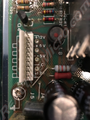
Below are thermal images of your standard Apple II power supply and related temperatures of parts under normal operation. These are the most critical parts, usually involved with regulation, and should ALL be replaced when rebuilding a power supply. The extremely high temperatures are common within all Apple II power supplies, and why we recommend most parts are exchanged for similar units but with larger ratings and capacity. None of these parts however are capacitors.
-
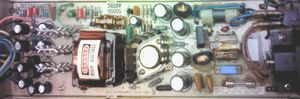 Example of Apple II power supply.
 -
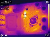 Thermal image of front parts of power supply.
92.6c / 199F -
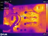 Thermal image of middle parts of power supply.
50.2c / 122F -
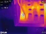 Thermal image of end parts of power supply.
72.4c / 162F


KFEST 2016 Session Outlining Project
Henry from ReActiveMicro presented the "Universal PSU Kit" sessions while at KFEST. His Ultimate-Micro partner, Anthony Martino, introduced the session.
Support: Connect AC To The Universal PSU
The Universal PSU is powered by 90-264VAC, 47-63Hz. Under full 63w load it consumes 1.6A at 100v, and 1A at 230v.
To connect the AC power first locate the correct connector on the Universal PSU (see pictures below).
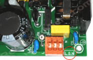
Connect the wires as shown. The Black or Brown (Live) wire will connect on the end of the connector closest to the large capacitor. Ground is typically supplied by the Apple II's PSU enclosure and is usually not connected. You can however connect it if you wish.
-
 AC Connections v1.0 - v1.1
 -
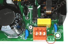 AC Connections v1.2 - v1.3
L=Live/Hot (left), G=Ground, N=Neutral (right)

Support: Connect DC Output Cable To The Universal PSU
The Universal PSU will output 63W max at full load: +5v @ 6A, +12v @ 3A.
To connect the DC Output Cable first locate the correct connector on the Universal PSU (see pictures below).
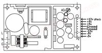
The newer revisions of the Universal PSU have two connectors, MTA and Sping. The MTA-156 connectors have the same pinouts across all versions. This allows simple use of a standard DC Output Cable. The spring connector pinout is shown below. There is also a legend printed on the top of the PCB as well as on the bottom to make connection as save and foll-proof as possible. Please be sure to recheck your connections with a multi-meter to ensure they are have the correct voltages or you risk destroying your Apple beyond repair!
Typically the colors Apple used for the II are as follows:
- +12v: Yellow (sometimes White with Orange Stripe) (Pin 1 on MTA connector)
- +5v: Orange (Pin 2 or 3 on MTA connector)
- Ground: Black (Pin 4 or 5 on MTA connector)
- -12v: Green (sometimes White with Blue Stripe) (Pin 6 on MTA connector)
- -5v: Blue (Pin 7 or 8 on MTA connector)
-
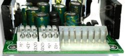
 MTA DC Connections v1.0 - v1.3
 -
 DC Spring Connections v1.3
 -
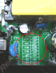 DC Pinout Legend v1.3 PCB
Left=Spring, Right=MTA


Installation Guide
- The Most Current Manual And Software
-
 Current Universal PSU Kit Installation Guide
