Disk II+

Disk ][+ is an electronic device that takes place into Disk ][ drives, the floppy disk drives used on the Apple ][ family computers. Its purpose is to replace the red LED of the drives by a two-color LED, in order to distinguish the reading phases, in green, from the writing phases, in red.
Disk ][+ has been designed with the idea of not being intrusive, which means that you can put it off from your drive if you want to give it its genuine aspect.
It is sold as a kit to build yourself, or already assembled and ready to be set up in your drive.
The way it works relies on the Disk ][ analogic board. This makes Disk ][+ compliant with all Apple ][ models that are able to be connected to a Disk ][ drive. Until now, the tests have been realized on Apple ][+, ][ Europlus and //e.
Moreover, every assembled unit of Disk ][+ has been tested and is guaranteed to work properly.
Inventory
If you have bought an assembled unit, you have received Disk ][+ with a velcro tape, in accordance with figure 1. Go to the Disk ][+ installation chapter directly.
If you have bought Disk ][+ as a kit to build yourself, you have received 3 packets, see figure 2.
-
![Figure 1: An assembled unit of Disk ][+](//wiki.reactivemicro.com/images/thumb/1/15/Image2.jpg/225px-Image2.jpg) Figure 1: An assembled unit of Disk ][+
Figure 1: An assembled unit of Disk ][+ -
![Figure 2: The 3 packets of a Disk ][+ kit](//wiki.reactivemicro.com/images/thumb/a/ae/Image3.jpg/400px-Image3.jpg) Figure 2: The 3 packets of a Disk ][+ kit
Figure 2: The 3 packets of a Disk ][+ kit
![Figure 1: An assembled unit of Disk ][+](/File:Image2.jpg)
![Figure 2: The 3 packets of a Disk ][+ kit](/File:Image3.jpg)
These 3 packets contain the following parts.
-
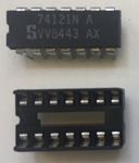 1 integrated circuit and its socket
 -
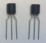 2 transistors
 -
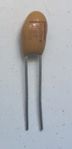 1 tantalum capacitor
 -
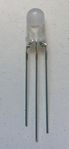 1 two-color LED
 -
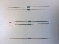 5 resistors
 -
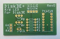 1 printed circuit board
 -
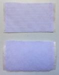 1 velcro in 2 pieces
 -
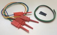 4 hook probes, 1 three-wire ribbon cable (red-black-green) and 3 heat shrink sleeves


Assembly instructions
Nomenclature
Nomenclature and components implementation are silk-screen printed on the printed circuit board.
| R1 | 120Ω resistance, color code: brown-red-brown |
| R2 | 3,3kΩ resistance, color code: orange-orange-red |
| R3 | 3,3kΩ resistance, color code: orange-orange-red |
| R4 | 10kΩ resistance, color code: brown-black-orange |
| R5 | 10kΩ resistance, color code: brown-black-orange |
| C1 | 10μF tantalum capacitor |
| Qg | PN2222A transistor |
| Qr | PN2222A transistor |
| 74121N | 74121N integrated circuit |
| GA | Green anode of the two-color LED |
| C | Cathode of the two-color LED |
| RA | Red anode of the two-color LED |
| Q1c | Hook probe to Q1 collector on the analogic board of the drive |
| C4+ | Hook probe to the positive lead of the C4 capacitor on the analogic board of the drive |
| C2- | Hook probe to the negative lead of the C2 capacitor on the analogic board of the drive |
| R16 | Hook probe to R16 resistance lead (on the 74LS125 IC side) on the analogic board of the drive |
Fitting orientation of the components
Some of the electronic components of this kit are polarized, or need to be placed in a certain direction. Pay attention when you solder them.
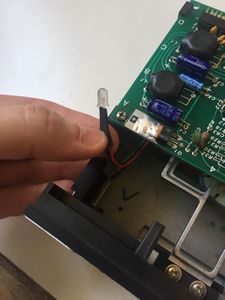
The tantalum capacitor is polarized, a small + sign indicates its positive lead, see figure 3. There is a + sign on the printed circuit board, too.
The transistors need to be placed in a certain direction. They have got a flat side and a round one, see figure 4. The flat side and the round side is drawn on the printed circuit board.
The integrated circuit, like its socket, has got a notch identified by the red point on figure 5 and 6. These notches have to be directed to the top edge of the printed circuit board (which represents it by a small break in the solid line).
Lastly, the two-color LED is polarized and has to be placed in a certain direction. The center lead is the common cathode, represented by a C, on which the black wire of the three-wire ribbon cable will be soldered. The medium size lead is the red anode (red wire), the shorter lead is the green anode (green wire). See figure 7.
-
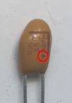 Figure 3: Polarity of the tantalum capacitor
 -
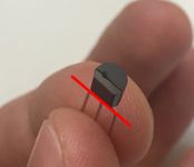 Figure 4: Flat side of the transistors
 -
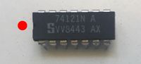 Figure 5: Notch of the integrated circuit
 -
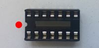 Figure 6: Notch of the socket
 -
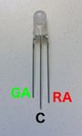 Figure 7: The 3 leads of the two-color LED


Soldering the kit
In order to make soldering easier, solder the lowest components first, the highest at the end:
- R1 to R5 resistances
- The integrated circuit socket, notch on the top edge side of the printed circuit board
- Qr and Qg transistors, their flat side on the top edge side of the printed circuit board
- C1, with the positive lead on the right edge side of the printed circuit board
Strip the wires of the hook probes (on the opposite side of the hook probes), tin them and solder them on the printed circuit board. The colors of the wires are not important.
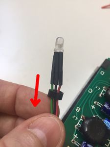
Take the three-wire ribbon cable. Separate the 3 wires on 1.5 inch on one side of the ribbon cable. Strip them and tin them. Put a heat shrink sleeve around each of the three wires. Take the two-color LED, shorten its lead half their size with a pair of cutting pliers. See figure 8. By doing this, take care to keep the size difference of the 3 leads to be able to distinguish them again later.
-
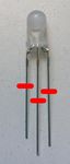 Figure 8: Shortening the LED leads

Solder the green wire of the ribbon cable on the shorten lead of the LED. Solder the black wire of the ribbon cable on the center lead (the longest one) of the LED. Solder the red wire of the ribbon cable on the middle size lead of the LED.
Once it is cold, pull the sleeves up to make them cover the LED leads, and heat them with a hair drier until they shrink. See figure 9.
-
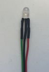 Figure 9: Soldering the three-wire ribbon cable and positioning the heat shrink sleeves

Separate the 3 wires on 0.5 inch on the other side of the ribbon cable. Strip them and tin them. Solder them on the printed circuit board and respect this implementation: the green wire on GA, the black wire on C and the red wire on RA.
Insert the 74121N integrated circuit on its socket, with its notch orientated to the top edge of the printed circuit board, like the socket.
Congratulations, your Disk ][+ kit is ready to be installed. See figure 10 and 11.
-
![Figure 10: Disk ][+ kit once it is assembled](//wiki.reactivemicro.com/images/thumb/c/cd/Image19.jpg/400px-Image19.jpg) Figure 10: Disk ][+ kit once it is assembled
Figure 10: Disk ][+ kit once it is assembled -
![Figure 11: Disk ][+ kit once it is assembled](//wiki.reactivemicro.com/images/thumb/2/23/Image20.jpg/399px-Image20.jpg) Figure 11: Disk ][+ kit once it is assembled
Figure 11: Disk ][+ kit once it is assembled
![Figure 10: Disk ][+ kit once it is assembled](/File:Image19.jpg)
![Figure 11: Disk ][+ kit once it is assembled](/File:Image20.jpg)
Disk ][+ installation in the drive
Follow these instructions step by step, it will help you installing your Disk ][+.
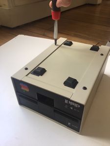
| 1. Disconnect your Disk ][ drive from your Apple ][. |  |
| 2. Flip it back. |  |
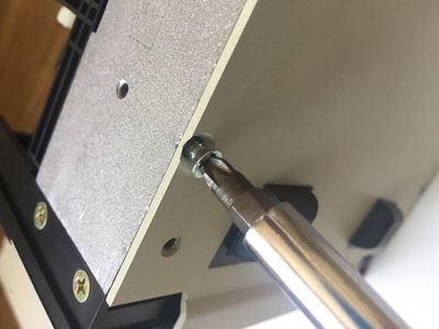
| 3. Unscrew the 4 screws that hold the upper part of the metal case. |  |
| 4. Flip it to its initial position. Make the upper part of the metal case slide by pushing it to the rear. |  |
| 5. Here is the inside of your Disk ][. |  |
| X | |
| X | |
| X | |
| X | |
| X |
-
-
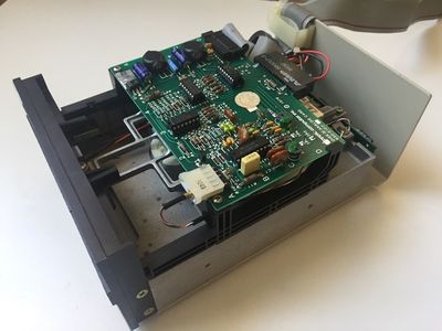
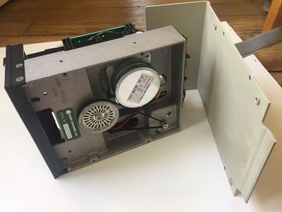
![This printed circuit board is the analogic card of your Disk ][ that drives the motor and the read/write process on the floppy disks.](//wiki.reactivemicro.com/images/thumb/a/ab/Image26.jpg/400px-Image26.jpg) This printed circuit board is the analogic card of your Disk ][ that drives the motor and the read/write process on the floppy disks.
This printed circuit board is the analogic card of your Disk ][ that drives the motor and the read/write process on the floppy disks. -
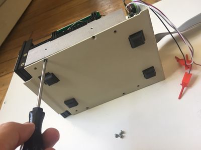
 Flip the drive on its left side.
 -
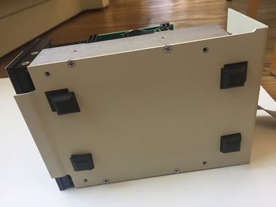
 Unscrew the 4 screws that hold the lower part of the metal case.
 -
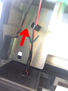
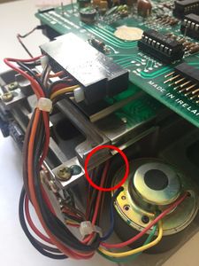
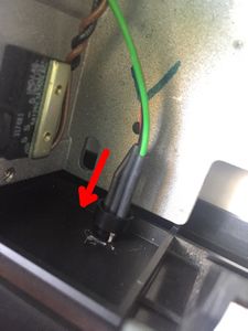
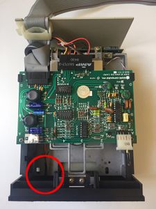 Lay your drive flat again. Now, we are going to extract the red LED of the drive. See the red circle on the photo.
 -
 Spot the plastic ring that surrounds the LED on the inside face of the plastic front panel. See the red circle on the photo.
 -
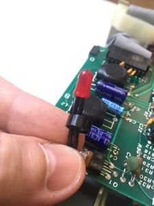
 Make a light lever movement with a small flat tool, like a screwdriver, to unclip this plastic ring carefully.
 -
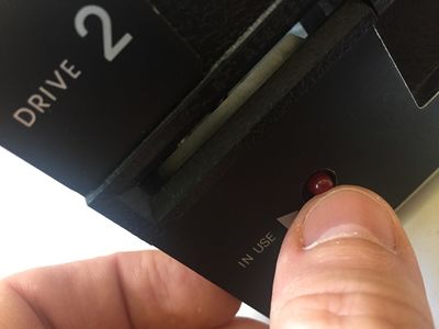 On the outside face of the plastic front panel, put a pressure on the red LED with your thumb in order to push it inside the drive, until the LED unclips.
 -
 The red LED is unclipped. Remove the plastic ring.
 -
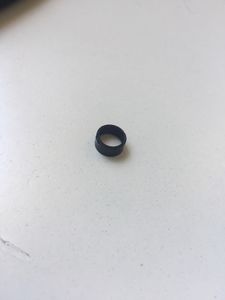 Keep it preciously, we will put it back later.
 -
 Flip the drive on its left side again.
 -
![Extract the red LED by the bottom of the drive. Please note that on the oldest Disk ][ drives, the frame can possibly not be perforated like the photo shows it. According to that, the red LED cable do not go under through the first frame hole, and do not go over through the second frame hole. If you are in this situation, the LED cable stays on the upper face of the frame. It is not a problem: unlike the photos, you will hide the red LED on the upper face of the frame, and you will run the new two-color LED and its cable on the upper face too, some steps later in this installation guide.](//wiki.reactivemicro.com/images/thumb/6/6c/Image36.jpg/225px-Image36.jpg) Extract the red LED by the bottom of the drive. Please note that on the oldest Disk ][ drives, the frame can possibly not be perforated like the photo shows it. According to that, the red LED cable do not go under through the first frame hole, and do not go over through the second frame hole. If you are in this situation, the LED cable stays on the upper face of the frame. It is not a problem: unlike the photos, you will hide the red LED on the upper face of the frame, and you will run the new two-color LED and its cable on the upper face too, some steps later in this installation guide.
Extract the red LED by the bottom of the drive. Please note that on the oldest Disk ][ drives, the frame can possibly not be perforated like the photo shows it. According to that, the red LED cable do not go under through the first frame hole, and do not go over through the second frame hole. If you are in this situation, the LED cable stays on the upper face of the frame. It is not a problem: unlike the photos, you will hide the red LED on the upper face of the frame, and you will run the new two-color LED and its cable on the upper face too, some steps later in this installation guide. -
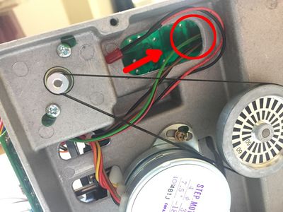
![Roll the red LED and its cable to make them fit in the compartment of the frame, as the photo shows it. The LED should stand alone this way. You can keep it in place with some scotch tape if you want. Take care not to obstruct the movement of the belt that drives the black and white wheel. If you own a very old Disk ][ and your LED cable runs on the upper face of the frame, you can easily find a place to house the LED too.](//wiki.reactivemicro.com/images/thumb/9/94/Image37.jpg/400px-Image37.jpg) Roll the red LED and its cable to make them fit in the compartment of the frame, as the photo shows it. The LED should stand alone this way. You can keep it in place with some scotch tape if you want. Take care not to obstruct the movement of the belt that drives the black and white wheel. If you own a very old Disk ][ and your LED cable runs on the upper face of the frame, you can easily find a place to house the LED too.
Roll the red LED and its cable to make them fit in the compartment of the frame, as the photo shows it. The LED should stand alone this way. You can keep it in place with some scotch tape if you want. Take care not to obstruct the movement of the belt that drives the black and white wheel. If you own a very old Disk ][ and your LED cable runs on the upper face of the frame, you can easily find a place to house the LED too. -
![Now, take your Disk ][+ printed circuit board and the wooly part of the velcro.](//wiki.reactivemicro.com/images/thumb/f/ff/Image38.jpg/225px-Image38.jpg) Now, take your Disk ][+ printed circuit board and the wooly part of the velcro.
Now, take your Disk ][+ printed circuit board and the wooly part of the velcro. -
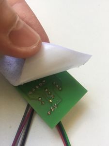 On the velcro, peel the protective film off. Stick the velcro to the rear of the printed circuit board.
 -
![The rear of your Disk ][+ is ready.](//wiki.reactivemicro.com/images/thumb/5/5b/Image40.jpg/225px-Image40.jpg) The rear of your Disk ][+ is ready.
The rear of your Disk ][+ is ready. -
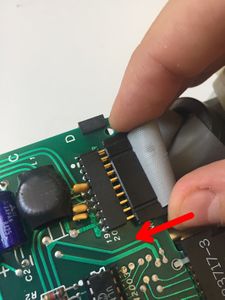
![Come back to the Disk ][ drive. Disconnect the ribbon cable from the analogic board and put the lower part of the metal case away.](//wiki.reactivemicro.com/images/thumb/5/58/Image41.jpg/225px-Image41.jpg) Come back to the Disk ][ drive. Disconnect the ribbon cable from the analogic board and put the lower part of the metal case away.
Come back to the Disk ][ drive. Disconnect the ribbon cable from the analogic board and put the lower part of the metal case away. -
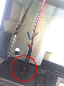
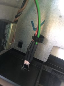
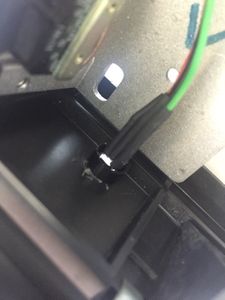
 All the cables from the drive are going through a hole on the side of the frame. Locate this hole. See the red circle on the photo.
 -
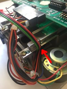 Make your new two-color LED and its three-wire ribbon cable go through this hole.
 -
![Flip the frame on its side and pull the LED and its three-wire ribbon cable. As previously explained, if you own a very old Disk ][, this hole in the frame will not exist and the LED and its cable will have to run on the upper face of the frame.](//wiki.reactivemicro.com/images/thumb/2/26/Image44.jpg/225px-Image44.jpg) Flip the frame on its side and pull the LED and its three-wire ribbon cable. As previously explained, if you own a very old Disk ][, this hole in the frame will not exist and the LED and its cable will have to run on the upper face of the frame.
Flip the frame on its side and pull the LED and its three-wire ribbon cable. As previously explained, if you own a very old Disk ][, this hole in the frame will not exist and the LED and its cable will have to run on the upper face of the frame. -
 Go through the second hole with your two- color LED. Follow the same path than the one your red LED was following previously.
 -
 Here is your new two-color LED, ready to replace the red LED.
 -
 Put the plastic ring back around your LED.
 -
 Insert the LED into the hole provided for this purpose.
 -
![Put a pressure carefully on the back of the LED until it clips into the socket. For instance, you can use a small screwdriver to help you (see the photo). If you own a very old Disk ][, this operation could be a bit difficult. So, if you are in this situation, unscrew the plastic front panel of the drive (2 screws on the left side, 2 screws on the right side). You will access to the LED more easily and you will save time.](//wiki.reactivemicro.com/images/thumb/7/7f/Image49.jpg/225px-Image49.jpg) Put a pressure carefully on the back of the LED until it clips into the socket. For instance, you can use a small screwdriver to help you (see the photo). If you own a very old Disk ][, this operation could be a bit difficult. So, if you are in this situation, unscrew the plastic front panel of the drive (2 screws on the left side, 2 screws on the right side). You will access to the LED more easily and you will save time.
Put a pressure carefully on the back of the LED until it clips into the socket. For instance, you can use a small screwdriver to help you (see the photo). If you own a very old Disk ][, this operation could be a bit difficult. So, if you are in this situation, unscrew the plastic front panel of the drive (2 screws on the left side, 2 screws on the right side). You will access to the LED more easily and you will save time. -
 Your new LED is set up.
 -
 Press with your finger around the plastic ring to clip it around the LED socket. Again, if there is any problem to put the plastic ring back, unscrew the plastic front panel of the drive. This could make things a lot easier.
 -
 Your new two-color LED is securely fixed.
 -
 Let’s go back to the rear of the drive.
 -
 Connect the ribbon cable back. Take care to connect it in the right direction. Take care not to shift the two connectors: this could destroy some chips on the analogic board.
 -
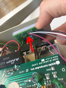
![Pull gently on the three-wire ribbon cable of the two- color LED, so that the cable is not too loose inside the drive. If you own a very old Disk ][ drive without holes in the frame, your LED cable runs through the upper face of the frame. Then do not pull it too much.](//wiki.reactivemicro.com/images/thumb/2/2f/Image55.jpg/225px-Image55.jpg) Pull gently on the three-wire ribbon cable of the two- color LED, so that the cable is not too loose inside the drive. If you own a very old Disk ][ drive without holes in the frame, your LED cable runs through the upper face of the frame. Then do not pull it too much.
Pull gently on the three-wire ribbon cable of the two- color LED, so that the cable is not too loose inside the drive. If you own a very old Disk ][ drive without holes in the frame, your LED cable runs through the upper face of the frame. Then do not pull it too much. -
![Take the rough part of the velcro and set it on the wooly part, at the rear of the Disk ][+ printed circuit board.](//wiki.reactivemicro.com/images/thumb/3/3e/Image56.jpg/225px-Image56.jpg) Take the rough part of the velcro and set it on the wooly part, at the rear of the Disk ][+ printed circuit board.
Take the rough part of the velcro and set it on the wooly part, at the rear of the Disk ][+ printed circuit board. -
 Peel the protective film off and stick the printed circuit board at the rear of your drive, in the upper right corner. See the photo.
 -
 Screw the lower part of the metal case back with the 4 flat-head screws.
 -
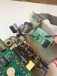
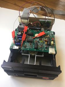
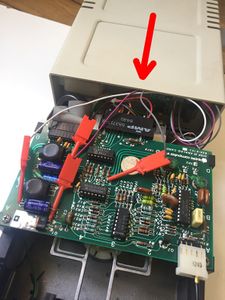
![Here is how things look.Now, you are going to connect the 4 hook probes to the analogic board. Everything is detailed below, step by step. According to the kind of Disk ][ you own, some components on the analogic board may vary in size, particularly selfs and capacitors. Sometimes, this could lead you to connect the hook probes in a different position than the ones shown on the photos. Just choose the position that suits you, the only important thing is to connect the hook probes on the right components leads.](//wiki.reactivemicro.com/images/thumb/2/26/Image59.jpg/225px-Image59.jpg) Here is how things look.Now, you are going to connect the 4 hook probes to the analogic board. Everything is detailed below, step by step. According to the kind of Disk ][ you own, some components on the analogic board may vary in size, particularly selfs and capacitors. Sometimes, this could lead you to connect the hook probes in a different position than the ones shown on the photos. Just choose the position that suits you, the only important thing is to connect the hook probes on the right components leads.
Here is how things look.Now, you are going to connect the 4 hook probes to the analogic board. Everything is detailed below, step by step. According to the kind of Disk ][ you own, some components on the analogic board may vary in size, particularly selfs and capacitors. Sometimes, this could lead you to connect the hook probes in a different position than the ones shown on the photos. Just choose the position that suits you, the only important thing is to connect the hook probes on the right components leads. -
![First, locate the hook probe that is identified as C2- on the Disk ][+. Take it and press on the rectangle part of the probe while you hold it in your fingers. A small metal hook is coming out from the top of the probe. Connect this first hook probe on the negative lead of the C2 capacitor on the analogic board. Release the probe and the hook is going to tighten itself around the capacitor lead.](//wiki.reactivemicro.com/images/thumb/5/53/Image60.jpg/225px-Image60.jpg) First, locate the hook probe that is identified as C2- on the Disk ][+. Take it and press on the rectangle part of the probe while you hold it in your fingers. A small metal hook is coming out from the top of the probe. Connect this first hook probe on the negative lead of the C2 capacitor on the analogic board. Release the probe and the hook is going to tighten itself around the capacitor lead.
First, locate the hook probe that is identified as C2- on the Disk ][+. Take it and press on the rectangle part of the probe while you hold it in your fingers. A small metal hook is coming out from the top of the probe. Connect this first hook probe on the negative lead of the C2 capacitor on the analogic board. Release the probe and the hook is going to tighten itself around the capacitor lead. -
![Now you are going to connect the hook probe named Q1c on the Disk ][+ printed circuit board. Connect it on the collector of the Q1 transistor on the analogic board. The collector of the transistor is the closest lead from the C4 capacitor. To save some space, a good idea consists in making the probe go under the C4 lead if you can. See photo.](//wiki.reactivemicro.com/images/thumb/b/bd/Image61.jpg/225px-Image61.jpg) Now you are going to connect the hook probe named Q1c on the Disk ][+ printed circuit board. Connect it on the collector of the Q1 transistor on the analogic board. The collector of the transistor is the closest lead from the C4 capacitor. To save some space, a good idea consists in making the probe go under the C4 lead if you can. See photo.
Now you are going to connect the hook probe named Q1c on the Disk ][+ printed circuit board. Connect it on the collector of the Q1 transistor on the analogic board. The collector of the transistor is the closest lead from the C4 capacitor. To save some space, a good idea consists in making the probe go under the C4 lead if you can. See photo. -
![Now, connect the third hook probe named C4+ on the Disk ][+ printed circuit board. Connect it on the positive lead of the C4 capacitor on the analogic board.](//wiki.reactivemicro.com/images/thumb/d/dc/Image62.jpg/225px-Image62.jpg) Now, connect the third hook probe named C4+ on the Disk ][+ printed circuit board. Connect it on the positive lead of the C4 capacitor on the analogic board.
Now, connect the third hook probe named C4+ on the Disk ][+ printed circuit board. Connect it on the positive lead of the C4 capacitor on the analogic board. -
![Then, locate and connect the last hook probe named R16 on the Disk ][+ printed circuit board. Connect it on the R16 resistance lead on the analogic board. Take care: the proper lead is the closest from the 74LS125 integrated circuit.](//wiki.reactivemicro.com/images/thumb/5/55/Image63.jpg/225px-Image63.jpg) Then, locate and connect the last hook probe named R16 on the Disk ][+ printed circuit board. Connect it on the R16 resistance lead on the analogic board. Take care: the proper lead is the closest from the 74LS125 integrated circuit.
Then, locate and connect the last hook probe named R16 on the Disk ][+ printed circuit board. Connect it on the R16 resistance lead on the analogic board. Take care: the proper lead is the closest from the 74LS125 integrated circuit. -
 Congratulations, it is done. Here is how things look like now. At this stage, insert a floppy disk carefully into the drive to check that there is not any cable hindering the floppy disk movement.
 -
 Put the upper part of the metal case back. Insert it from the rear and make it slide gently. Take care not to unclip the hook probes.
 -
 Once the metal case reaches its position, flip your drive and screw the 4 screws back.
 -
![Your Disk ][ is upgraded an ready !](//wiki.reactivemicro.com/images/thumb/f/f2/Image67.jpg/225px-Image67.jpg) Your Disk ][ is upgraded an ready !
Your Disk ][ is upgraded an ready ! -
![Connect it back to your Apple ][, and perform a test. The LED is off when there is no activity on the drive.](//wiki.reactivemicro.com/images/thumb/a/a7/Image68.jpg/400px-Image68.jpg) Connect it back to your Apple ][, and perform a test. The LED is off when there is no activity on the drive.
Connect it back to your Apple ][, and perform a test. The LED is off when there is no activity on the drive. -
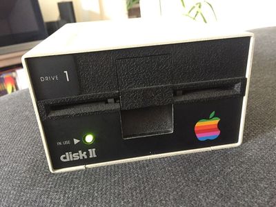 It is green when the drive is reading a floppy disk.
 -
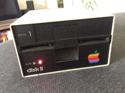 It is red when the drive is writing on the floppy disk.
![This printed circuit board is the analogic card of your Disk ][ that drives the motor and the read/write process on the floppy disks.](/File:Image26.jpg)


![Extract the red LED by the bottom of the drive. Please note that on the oldest Disk ][ drives, the frame can possibly not be perforated like the photo shows it. According to that, the red LED cable do not go under through the first frame hole, and do not go over through the second frame hole. If you are in this situation, the LED cable stays on the upper face of the frame. It is not a problem: unlike the photos, you will hide the red LED on the upper face of the frame, and you will run the new two-color LED and its cable on the upper face too, some steps later in this installation guide.](/File:Image36.jpg)
![Roll the red LED and its cable to make them fit in the compartment of the frame, as the photo shows it. The LED should stand alone this way. You can keep it in place with some scotch tape if you want. Take care not to obstruct the movement of the belt that drives the black and white wheel. If you own a very old Disk ][ and your LED cable runs on the upper face of the frame, you can easily find a place to house the LED too.](/File:Image37.jpg)
![Now, take your Disk ][+ printed circuit board and the wooly part of the velcro.](/File:Image38.jpg)

![The rear of your Disk ][+ is ready.](/File:Image40.jpg)
![Come back to the Disk ][ drive. Disconnect the ribbon cable from the analogic board and put the lower part of the metal case away.](/File:Image41.jpg)


![Flip the frame on its side and pull the LED and its three-wire ribbon cable. As previously explained, if you own a very old Disk ][, this hole in the frame will not exist and the LED and its cable will have to run on the upper face of the frame.](/File:Image44.jpg)


![Put a pressure carefully on the back of the LED until it clips into the socket. For instance, you can use a small screwdriver to help you (see the photo). If you own a very old Disk ][, this operation could be a bit difficult. So, if you are in this situation, unscrew the plastic front panel of the drive (2 screws on the left side, 2 screws on the right side). You will access to the LED more easily and you will save time.](/File:Image49.jpg)


![Pull gently on the three-wire ribbon cable of the two- color LED, so that the cable is not too loose inside the drive. If you own a very old Disk ][ drive without holes in the frame, your LED cable runs through the upper face of the frame. Then do not pull it too much.](/File:Image55.jpg)
![Take the rough part of the velcro and set it on the wooly part, at the rear of the Disk ][+ printed circuit board.](/File:Image56.jpg)


![Here is how things look.Now, you are going to connect the 4 hook probes to the analogic board. Everything is detailed below, step by step. According to the kind of Disk ][ you own, some components on the analogic board may vary in size, particularly selfs and capacitors. Sometimes, this could lead you to connect the hook probes in a different position than the ones shown on the photos. Just choose the position that suits you, the only important thing is to connect the hook probes on the right components leads.](/File:Image59.jpg)
![First, locate the hook probe that is identified as C2- on the Disk ][+. Take it and press on the rectangle part of the probe while you hold it in your fingers. A small metal hook is coming out from the top of the probe. Connect this first hook probe on the negative lead of the C2 capacitor on the analogic board. Release the probe and the hook is going to tighten itself around the capacitor lead.](/File:Image60.jpg)
![Now you are going to connect the hook probe named Q1c on the Disk ][+ printed circuit board. Connect it on the collector of the Q1 transistor on the analogic board. The collector of the transistor is the closest lead from the C4 capacitor. To save some space, a good idea consists in making the probe go under the C4 lead if you can. See photo.](/File:Image61.jpg)
![Now, connect the third hook probe named C4+ on the Disk ][+ printed circuit board. Connect it on the positive lead of the C4 capacitor on the analogic board.](/File:Image62.jpg)
![Then, locate and connect the last hook probe named R16 on the Disk ][+ printed circuit board. Connect it on the R16 resistance lead on the analogic board. Take care: the proper lead is the closest from the 74LS125 integrated circuit.](/File:Image63.jpg)


![Your Disk ][ is upgraded an ready !](/File:Image67.jpg)
![Connect it back to your Apple ][, and perform a test. The LED is off when there is no activity on the drive.](/File:Image68.jpg)


In case of troubles
The two-color LED stays off. Open your Disk ][ drive again, and check the positions of the hook probes. Are they connected to the right leads? Are they firmly connected around the leads? Close your Disk ][ drive and perform a new test.
The two-color LED makes a red light for reading and a green light for writing. The two-color LED has not been soldered correctly. Check between the LED and the three-wire ribbon cable, then check between the three-wire ribbon cable and the Disk ][+ printed circuit board. There is an inversion somewhere.
Disk ][+ works properly, but the LED makes a red light during the boot sequence, when the drive is roaring. The 74LS125 integrated circuit on your analogic board is becoming weak. It is one of the most fragile component on Disk ][ drives. For example, it does not stand when the drive ribbon cable is shifted when it is connected to the Apple ][ controller card. Change this 74LS125 before having more serious problems with your drive.