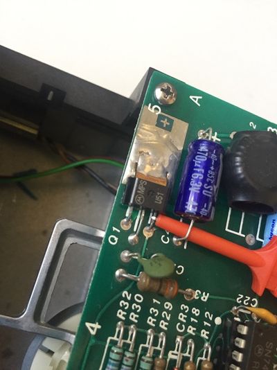
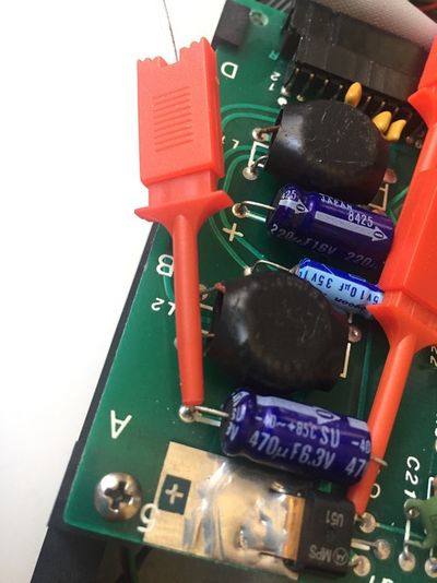
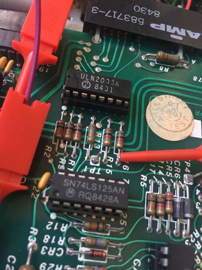
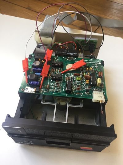
Disk II+
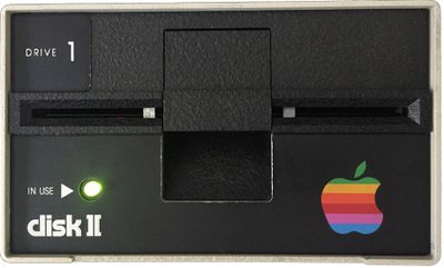
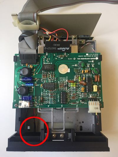
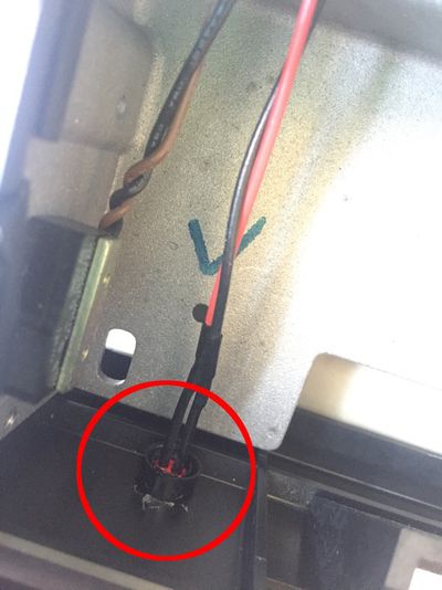
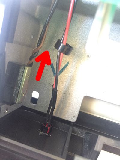
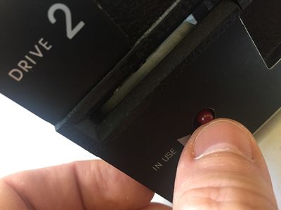
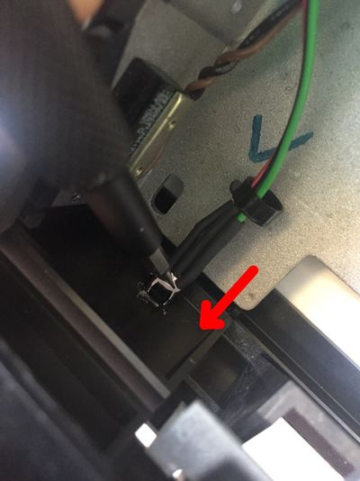
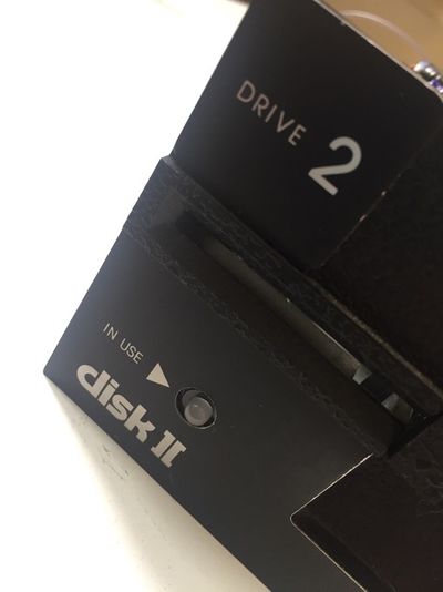
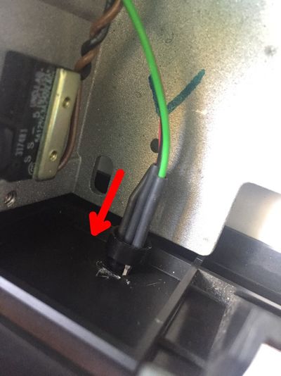
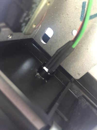
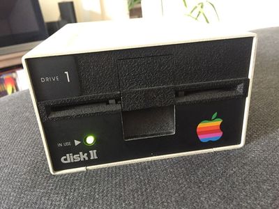
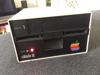
Disk ][+ was designed by Fabien Bénattou in 2018, and is based on the idea he discovered on an old website (credit unknown). It is an electronic device installed into Disk ][ drives, the floppy disk drives used on the Apple ][ family computers. Its purpose is to replace the red LED of the drives by a two-color LED, in order to distinguish the reading phases, in green, from the writing phases, in red.
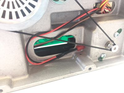
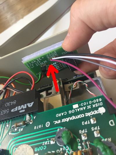
Disk ][+ has been designed with the idea of not being intrusive, which means that you can un-install from your drive if you want to give it its genuine aspect.
It is sold as a kit to build yourself, or already assembled and ready to be set up in your drive.
The way it works relies on the Disk ][ analogue board. This makes Disk ][+ compliant with all Apple ][ models that are able to be connected to a Disk ][ drive. Until now, the tests have been performed on Apple ][+, ][ Europlus and //e.
Moreover, every assembled unit of Disk ][+ has been tested and is guaranteed to work properly.
Project Status: Complete. In production. Actively sold by ReActiveMicro as of end of January 2019.
Support: Post on the Discussion page (link above) or email ReActiveMicro Support.
Sales: Visit the ReActiveMicro Store.
Versions
Fabien Bénattou created the first prototype and announced it on the Apple II Enthusiasts group on Facebook on June 10th, 2018.
Fabien contacted ReActiveMicro on June 25th about his project and asked about a partnership and selling it through through the Store. v1.0 of the project was released for sale by ReActiveMicro on January 24th, 2019.
Inventory
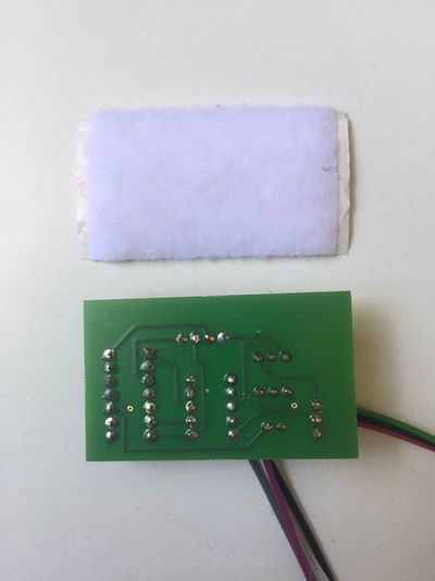
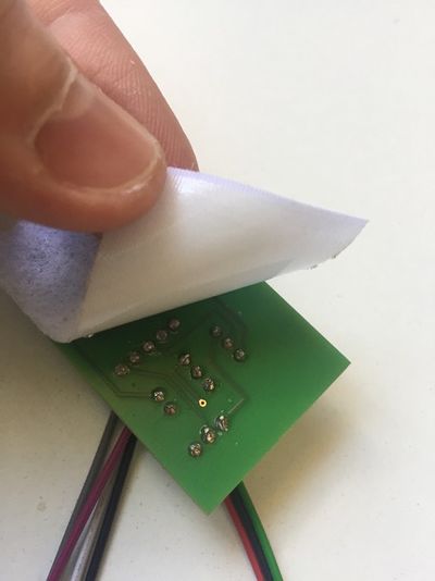
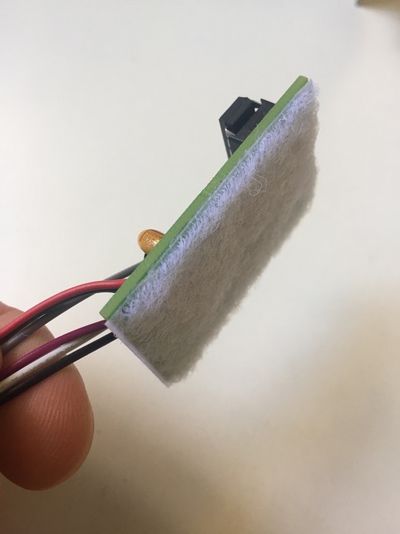
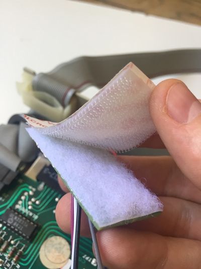
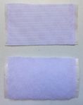
If you have bought an assembled unit, you have received Disk ][+ with a velcro tape, in accordance with figure 1. Go to the Disk ][+ installation chapter directly.
If you have bought Disk ][+ as a kit to build yourself, you have received 3 packets, see figure 2.
-
Figure 1: An assembled unit of Disk ][+
-
Figure 2: The 3 packets of a Disk ][+ kit
These 3 packets contain the following parts.
-
1 integrated circuit and its socket
-
2 transistors
-
1 tantalum capacitor
-
1 two-color LED
-
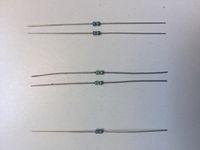
5 resistors
-
1 printed circuit board
-
1 velcro in 2 pieces
-
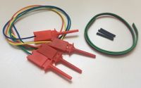
4 hook probes, 1 three-wire ribbon cable (red-black-green) and 3 heat shrink sleeves
Assembly instructions
Nomenclature
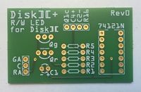
Nomenclature and components implementation are silk-screen printed on the printed circuit board.
| R1 | 120Ω resistance, color code: brown-red-brown |
| R2 | 3,3kΩ resistance, color code: orange-orange-red |
| R3 | 3,3kΩ resistance, color code: orange-orange-red |
| R4 | 10kΩ resistance, color code: brown-black-orange |
| R5 | 10kΩ resistance, color code: brown-black-orange |
| C1 | 10μF tantalum capacitor |
| Qg | PN2222A transistor |
| Qr | PN2222A transistor |
| 74121N | 74121N integrated circuit |
| GA | Green anode of the two-color LED |
| C | Cathode of the two-color LED |
| RA | Red anode of the two-color LED |
| Q1c | Hook probe to Q1 collector on the analogic board of the drive |
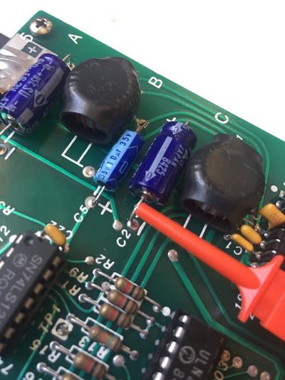
| C4+ | Hook probe to the positive lead of the C4 capacitor on the analogic board of the drive |
| C2- | Hook probe to the negative lead of the C2 capacitor on the analogic board of the drive |
| R16 | Hook probe to R16 resistance lead (on the 74LS125 IC side) on the analogic board of the drive |
Fitting orientation of the components
Some of the electronic components of this kit are polarized, or need to be placed in a certain direction. Pay attention when you solder them.
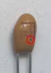
The tantalum capacitor is polarized, a small + sign indicates its positive lead, see figure 3. There is a + sign on the printed circuit board, too.
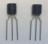
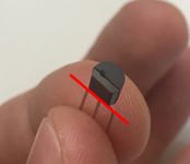
The transistors need to be placed in a certain direction. They have got a flat side and a round one, see figure 4. The flat side and the round side are drawn on the printed circuit board.
The integrated circuit, like its socket, has got a notch identified by the red point on figure 5 and 6. These notches have to be directed to the top edge of the printed circuit board (which represents it by a small break in the solid line).
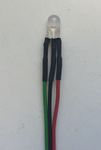
Lastly, the two-color LED is polarized and has to be placed in a certain direction. The center lead is the common cathode, represented by a C, on which the black wire of the three-wire ribbon cable will be soldered. The medium size lead is the red anode (red wire), the shorter lead is the green anode (green wire). See figure 7.
-
Figure 3: Polarity of the tantalum capacitor
-
Figure 4: Flat side of the transistors
-
Figure 5: Notch of the integrated circuit
-
Figure 6: Notch of the socket
-
Figure 7: The 3 leads of the two-color LED
Soldering the kit
In order to make soldering easier, solder the lowest components first, the highest at the end:
- R1 to R5 resistances
- The integrated circuit socket, notch on the top edge side of the printed circuit board
- Qr and Qg transistors, their flat side on the top edge side of the printed circuit board
- C1, with the positive lead on the right edge side of the printed circuit board
Strip the wires of the hook probes (on the opposite side of the hook probes), tin them and solder them on the printed circuit board. The colors of the wires are not important.
Take the three-wire ribbon cable. Separate the 3 wires on 1.5 inch on one side of the ribbon cable. Strip them and tin them. Put a heat shrink sleeve around each of the three wires. Take the two-color LED, shorten its lead half their size with a pair of cutting pliers. See figure 8. By doing this, take care to keep the size difference of the 3 leads to be able to distinguish them again later.
-
Figure 8: Shortening the LED leads
Solder the green wire of the ribbon cable on the shorten lead of the LED. Solder the black wire of the ribbon cable on the center lead (the longest one) of the LED. Solder the red wire of the ribbon cable on the middle size lead of the LED.
Once it is cold, pull the sleeves up to make them cover the LED leads, and heat them with a hair drier until they shrink. See figure 9.
-
Figure 9: Soldering the three-wire ribbon cable and positioning the heat shrink sleeves
Separate the 3 wires on 0.5 inch on the other side of the ribbon cable. Strip them and tin them. Solder them on the printed circuit board and respect this implementation: the green wire on GA, the black wire on C and the red wire on RA.
Insert the 74121N integrated circuit on its socket, with its notch orientated to the top edge of the printed circuit board, like the socket.
Congratulations, your Disk ][+ kit is ready to be installed. See figure 10 and 11.
-
Figure 10: Disk ][+ kit once it is assembled
-
Figure 11: Disk ][+ kit once it is assembled
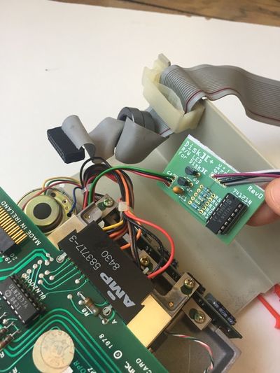
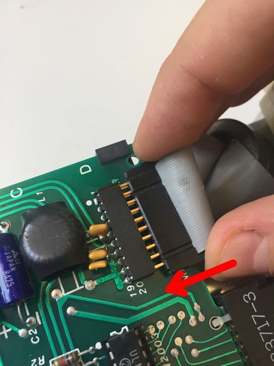
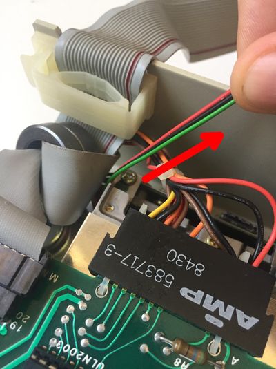
Disk ][+ installation in the drive
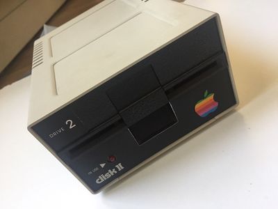
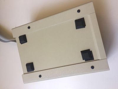
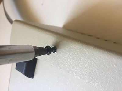
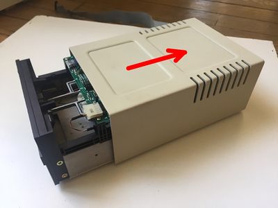
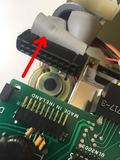
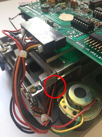
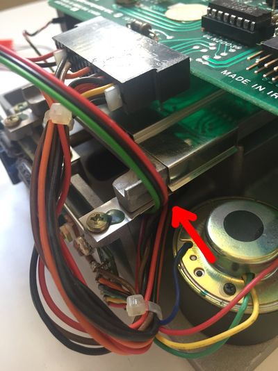
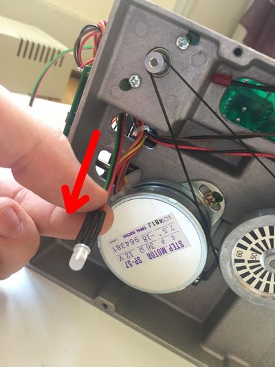
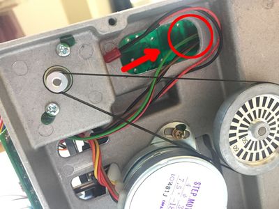
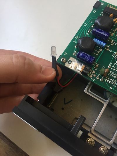
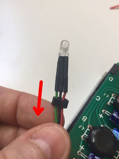
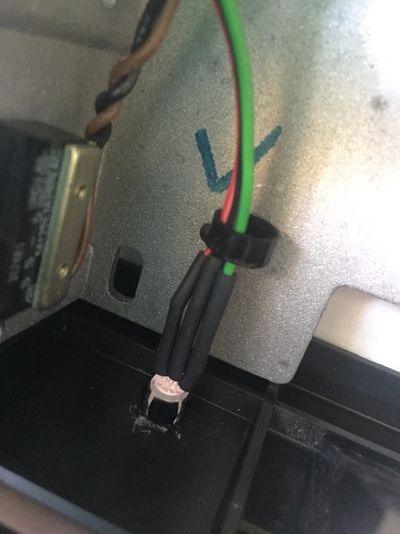
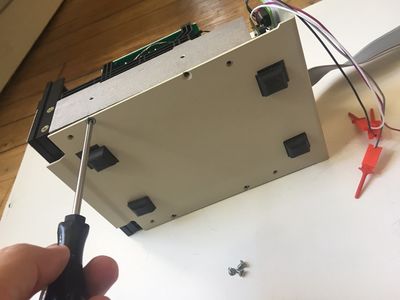
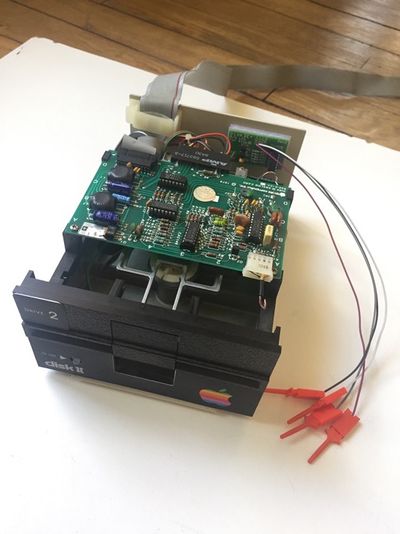
Follow these instructions step by step, it will help you installing your Disk ][+.
Troubleshooting
The two-color LED stays off. Open your Disk ][ drive again, and check the positions of the hook probes. Are they connected to the right leads? Are they firmly connected around the leads? Close your Disk ][ drive and perform a new test.
The two-color LED makes a red light for reading and a green light for writing. The two-color LED has not been soldered correctly. Check between the LED and the three-wire ribbon cable, then check between the three-wire ribbon cable and the Disk ][+ printed circuit board. There is an inversion somewhere.
Disk ][+ works properly, but the LED makes a red light during the boot sequence, when the drive is roaring. The 74LS125 integrated circuit on your analogic board is becoming weak. It is one of the most fragile component on Disk ][ drives. For example, it does not stand when the drive ribbon cable is shifted when it is connected to the Apple ][ controller card. Change this 74LS125 before having more serious problems with your drive.
Documentation
-
Installation Guide v1.1
![Figure 1: An assembled unit of Disk ][+](http://wiki.reactivemicro.com/images/thumb/1/15/Image2.jpg/225px-Image2.jpg)
![Figure 2: The 3 packets of a Disk ][+ kit](http://wiki.reactivemicro.com/images/thumb/a/ae/Image3.jpg/400px-Image3.jpg)




![Figure 10: Disk ][+ kit once it is assembled](http://wiki.reactivemicro.com/images/thumb/c/cd/Image19.jpg/400px-Image19.jpg)
![Figure 11: Disk ][+ kit once it is assembled](http://wiki.reactivemicro.com/images/thumb/2/23/Image20.jpg/399px-Image20.jpg)
