UltraWarp: Difference between revisions
Khaibitgfx (talk | contribs) No edit summary |
Khaibitgfx (talk | contribs) |
||
| Line 206: | Line 206: | ||
== Documentation == | == Documentation == | ||
<div class="new_window"> | <div class="new_window"> | ||
<gallery class="center" widths=150px heights=80 caption=" | <gallery class="center" widths=150px heights=80 caption="2019 Edition"> | ||
File:PDF_Logo_80x80.png|UltraWarp Manual|link=http://wiki.reactivemicro.com/images/1/13/UltraWarp_v1.91G_-_Users_Guide.pdf | File:PDF_Logo_80x80.png|UltraWarp Manual|link=http://wiki.reactivemicro.com/images/1/13/UltraWarp_v1.91G_-_Users_Guide.pdf | ||
</gallery> | </gallery> | ||
</div> | </div> | ||
Revision as of 09:57, 15 November 2019
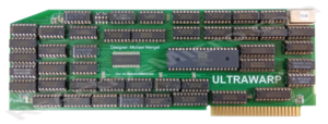
The UltraWarp is an accelerator board for the Apple II, IIplus, and //e systems. It was conceived, created, and designed by Michael Mengel. The name "UltraWarp" was trademarked by Michael on November 4th, 2010. US Serial Number:85168787, US Registration Number:4214564.
ReActiveMicro worked together with Michael to help bring the project to the Apple II Community, and was released for sale from the ReActiveMicro Store on June 13, 2017.
Product Status: Actively sold by ReActiveMicro.
Support: Post on the Discussion page (link above) or email ReActiveMicro Support.
Sales: Visit the ReActiveMicro Store.
History
Michael Mengel stated "Originally I designed the card on an Apple II+ and BASIS 108 to accelerate my favorite programs CHESS and CHECKERS, inspired by an article in Creative Computing Vol. 8 No. 12 Dec 1982 page 30 ("New Processors for The Apple")."
Michael has listed a few boards for sale on eBay, but never considered mass production.
On March 5th, 2017 Henry contacted Michael Mengel about helping bring his project to the Apple II Community. After some email exchanges and design reviews, a initial PCB order was placed by ReActiveMicro and soon after the boards were confirmed working and released for sale in the ReActiveMicro Store.
Versions
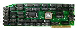
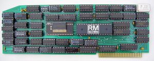
Michael produced a couple of versions of the UltraWarp board. The last and most current version was v1.91G and usually has the speed of 13MHz. Some boards however have been over clocked as much as 18MHz.
-
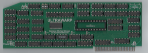
UltraWarp v1.92 distributed by Michael Mengel
-
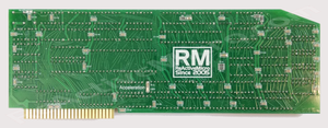
UltraWarp v1.91G distributed by Michael Mengel
-
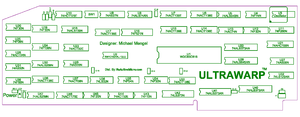
UltraWarp v1.91G IC Locations
ReActiveMicro has produced several versions of the UltraWarp board. The last and most current version was v1.91G and usually has the speed of 13MHz. v1.92 had a PLCC footprint CPU and 128K SATURN board support which was a common RAM card with more than 16Kb RAM for the II+ in the early 80's from TITAN Inc.
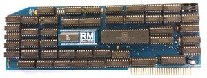
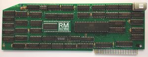
In June of 2017 Henry made a re-layout of the v1.91G version to move more parts to SMT which allows for a less costly assembly. This revised version was called UltraWarp v1.91RM, and 3 protos were ordered for verification of the new layout. This new design could also allow a kit version of the board to be produced and sold.
-
UltraWarp v1.91G distributed by ReActiveMicro (June 2017)
-
UltraWarp v1.91G distributed by ReActiveMicro (August 2017)
-
UltraWarp v1.91RM-Proto distributed by ReActiveMicro (August 2017)
-
UltraWarp v1.91RM distributed by ReActiveMicro (2017-12-20)
-
UltraWarp v1.91RM distributed by ReActiveMicro (2017-12-20)
UltraWarp v1.91RM Kit
In June of 2017 Henry created the "kit" version of the UltraWarp v1.91G project. The kit consists of the UltraWarp v1.91RM PCB, DIP sockets, and DIP ICs. The PCB contains some surface mount components which are already installed to allow for a simpler to assemble kit for beginners. The kit is exactly the same as an assembled board.
See #Reviews for Chris Torrence's Assembly Lines #58 video about basic assembly. He points out the following things to keep in mind.
- As many soldering points as there are, 796 to be exact, this is technically a beginners project. There are no special tools needed. If you can fill a hole with solder, then you can assemble this kit.
- Time required can range from 1 hour, to about 3 hours for really slow solders.
- Be sure to use an IC Pin Straightener or manualy adjust the ICs pins before inserting in to sockets.
- Using "No Clean" or "RMA" flux is most simple as the board will not need cleaning in most cases. If cleaning is required follow the directions for your type of flux.
- Be sure to install the socket "notches" as noted on the board, and of course install the ICs in the same direction.
- All ICs are listed on the PCBs for your reference.
- If you have any doubts about anything be sure to contact ReActiveMicro Support to clarify before continuing.
There are no other special instructions to follow when assembling the UltraWarp v1.91RM Kit.
If you have any issues start by checking for bent ICs pins. Next check solder joints. If all else fails contact ReActiveMicro Support.
-
UltraWarp v1.91RM 13MHz IC Listing
UltraWarp v1.91RM Features
- Full TTL IC design. This means the board can be very simply repaired and overclocked.
- Fused to protect against damage from bad or failing ICs.
- "Power" LED to show the Fuse is working and the board has power.
- "Acceleration" LED is ON to show when the board is running in fast mode, or OFF to show when the board is running at 1MHz.
- DIP Switch to slow down Slot 5, 7, and joystick if needed.
- Solder points on back near the Oscillator to run the board from the bus at 7MHz without any Oscillator installed. This is used for diagnostics if the Oscillator is suspected to be defective.
- Power and Acceleration LEDs. These are lit when active.
- Works in any open slot.
- Fully II and II+ compatible.
- 16bit 65816 CPU capable of running 16bit software.
Reviews
On December 26, 2017 Chris Torrence posted a review about the UltraWarp v1.91RM kit.
Other examples of software running at 1MHz and 13MHz on an Apple II Rev 4 Apple II with Integer Basic ROMs.
Thanks to Tony Bogan for the videos and help testing!
On August 31, 2017 Joe Strosnider posted an update to his original UltraWarp review. He now states the production UltraWarp v1.91RM is working 100% for all his testing at 13MHz.
On July 28th, 2017 Joe Strosnider reviews the UltraWarp v1.91G proto from ReActiveMicro. During his testing he found some issues at 13MHz which were later addressed in the production models. The card however worked fine at 12MHz.
Testing
There is currently no known test program designed for fully testing all aspects of accelerators. ReActiveMicro has been very Active in trying to commission a Community programmer to take up this task, however games and other such endeavors have taken priority and they were turned down by everyone spoken with. No programmer has even enounced the consideration of such a task. So it's with deep regret a test program probably won't happen and is probably beyond every programmer's ability in the Community. ReActiveMicro however will pay any programmer who creates such a program. Contact Support to discuss the project and payment options.
That being the case, users with accelerators need to resort to "testing" for most likely known issues. This isn't necessarily the full range of issues, just a way to test for some of the more common ones with the hope if there is an issue it will become more apparent.
To best test all versions of the UltraWarp accelerators users should perform the following tasks at full speed:
- Install a RAM board in the IIe Aux Slot and test for 10 minutes or more. This test seems to find 95% of issues.
- Run PublishIt4 with all overlays in RAMWorks III Aux memory. Open and close several example files (LETTER and INVOICE) and copy & paste the image/picture elements several times.
- Install a RAMFactor card and perform the self test Cx0AG in different slots (x=slot number).
- Test with XPS IIe Diagnostics, option A and O.
- Test with Flight Simulator II. The demo should run at least 10 minutes without any issues.
DMA And Known Issues
DMA stands for Direct Memory Access and is a feature of computer systems that allows certain hardware subsystems to access main system memory (Random-access memory), independent of the central processing unit (CPU).
Without DMA, when the CPU is using programmed input/output, it is typically fully occupied for the entire duration of the read or write operation, and is thus unavailable to perform other work. With DMA, the CPU first initiates the transfer, then it does other operations while the transfer is in progress, and it finally receives an interrupt from the DMA controller or card when the operation is done. This feature is useful at any time that the CPU cannot keep up with the rate of data transfer, or when the CPU needs to perform useful work while waiting for a relatively slow I/O data transfer.
The UltraWarp uses 128k of "fast RAM" to shadow the slower Apple II 64k main RAM, and Bank 0 of AUX RAM which is also 64k. It normally uses the fast RAM for processing and then updates the slower Apple II RAM when it's needed to keep the two synchronized. Some boards however will directly access RAM, update or change things, and the UltraWarp will not know this unless strict DMA rules are followed.
Some boards like the Video-Digitizer and WILDCARD use the DMA line but do not adhere correctly to the Apple II requirements when using DMA. Other cards like the MicroDrive/Turbo and RAMFast SCSI card correctly follow the Apple II requirements when using DMA and thus are 100% compatible with all other DMA accelerators.
Since there are so few boards capable of using DMA it is assumed the most common boards, MicroDrive/Turbo, RAMFast SCSI, and Apple II High Speed SCSI Card will all work correctly. If you have a board which only uses the /DMA line and does not also use the /RDY line, then it is a safe assumption the board will not work correctly with DMA accelerators.
Boards known to work correctly with DMA accelerators:
- MicroDrive/Turbo
- RAMFast SCSI Card
- Apple II High Speed SCSI Card
Boards known to NOT work correctly with DMA accelerators:
- Video-Digitizer
- WILDCARD
Controlling Speed
Like all accelerators for the Apple II, the UltraWarp can also be controlled by softswitches. There is also a Dip Switch which can control the slot speeds.
Location:
$C05D - Low speed (1 MHz)
$C05C - High speed (set on power-up)
$C05B - Disable
The following example in Applesoft Basic will slow the UW to the 1 MHz clock rate: POKE 49245,0
Next example switches back to full speed: POKE 49244,0
There is NO need for RESET after the SLOW-POKE or FAST-POKE.
DIP Switch Settings. All defaulted OFF. See the manual for details.
- SW1 = Nothing (not connected/unused).
- SW2 = Joystick Delay. When set ON accesses to $C070 cause a 2.5 millisecond delay.
- SW3 = When set ON controls delay on Slot 5 to 1MHz.
- SW4 = When set ON controls delay on Slot 7 to 1MHz.

