Apple II Plus Rev 7 RFI


The Apple II plus Rev 7 RFI motherboard replacement was started on April 20th, 2019 by Henry from ReActiveMicro, and was officially released on February 15th, 2020. The 27-Series version of the motherboard was officially released on April 1st, 2020.
This marks the first full computer product released by ReActiveMicro. The concept is a factory new replacement motherboard which is reliable and fully tested, to be used as a replacement for the original motherboard. This will allow the user a better experience and less issues moving forward. In contrast, most original motherboards now require constant maintenance in order to stay in a dependable running state. Compounding the situation, the original motherboard has low quality sockets, and old DRAMs and ICs which are power hungry and are well past their lifespan ratings.
Product Status: Actively sold by ReActiveMicro.
Support: Post on the Discussion page (link above) or email ReActiveMicro Support.
Sales: Visit the ReActiveMicro Store.
Kit Assembly
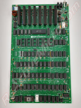
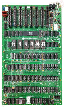
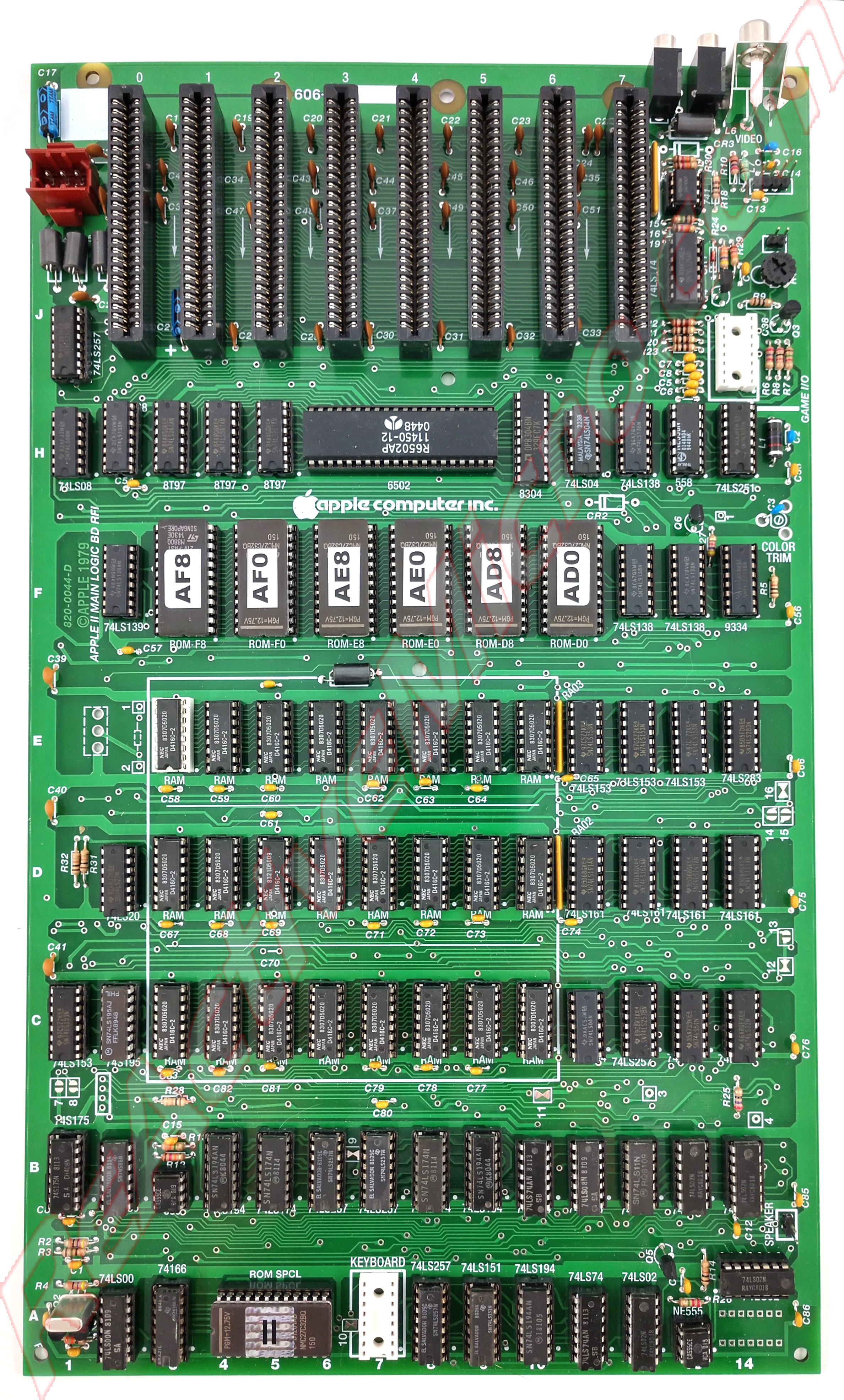
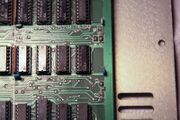
The Apple II plus Rev 7 RFI Kit is a total of 2160 pads or "solder joints" for the 93-Series kit, and 2174 pads for the 27-Series kit. It takes about 5 hours to fully assemble a kit if you have a decent iron, flux, and solder. The parts included with your kit and the PCB have basic labels. Those with intermediate knowledge should have little trouble assembling the kit from the labels on the parts, the bag, and the PCB. The images below of the motherboards can also be used for reference or to determine orientation, such as the diodes.
To assemble your kit we recommend adding parts in groups and then soldering them. This will be the fastest way to assemble the PCB rather than adding one part at a time then soldering it.
- Start with the small passive parts like caps and resistors. Some of the location labels will be hard to see if you start with the sockets or other parts. Each time a part is added you can simply bend over a leg on each side to help hold the part to the PCB which allows the board to be turned over and prevents parts from falling out. It is most simple to load all the parts in groups and then solder and clip the legs as needed.
- Once the passive parts are installed next should be the IC sockets. When a socket is loaded on the board bending the corner pins of the sockets helps hole it to the PCB which allows group loading and soldering. The sockets are all the same thickness. So if you solder on a flat surface then this will also help hold all the sockets flat to the PCB and give a more uniform appearance when completed. Be sure ALL pin 1 'notches' are facing towards the keyboard end. The CPU socket 'notch' should be towards the Game IO / Video side, and the ROM SPCL should be facing towards the crystal side.
- End with the larger parts, like jacks, and finally the slots. Don't bend over these parts pins/legs as they will be too hard. You will need to hold them in place as you solder a few pins before you can group solder.
A good loupe (magnifying glass) is recommended for helping identify and confirm parts, like the markings on some small caps. It also helps with solder joint inspection. An illuminated 40 x 25mm and a 35 x 50mm loupe are well worth the investment and can be had for about $10 each on eBay.
-
 93-Series ROM
 -
 27-Series ROM
On June 7th, 2020 Chris Torrence posted a build video of the Apple II plus Rev 7 RFI kit. We highly recommend watching the video before starting your kit as well as fully reviewing this Wiki page.
Note: Cautionary care needs to be taken while installing capacitors and diodes.
If your kit includes Aluminum or Tantalum capacitors, or "caps" for short, then be sure to install them in the correct orientation. The PCB will be clearly marked with "+" signs for all cap locations when the orientation of the part matters, or a polarized part is normally used. Sometimes a non-polarized part is used in place of a polarized one and then its orientation does not matter, however install a polarized cap backwards and you will damage it. An Aluminum Electrolytic will have a strip pointing to the NEGATIVE end lead. A Tantalum Electrolytic will generally have a marking or stripe to denote (not always pointing to) the POSITIVE lead.
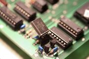
- Install the 10uF Aluminum caps at locations C17 and C27. Be sure to install correctly as they are polarized. All caps will have value markings on them. "106" is 10uF, and "104" is .1uF. 10uF is also typically physically larger than .1uF. This should help identify the ceramic caps in the kit. They along with the Electrolytic caps can also clearly be seen in the assembled pic above.
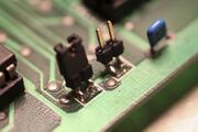
- Install a 47pF cap at location "C3 (COLOR TRIM)". This can be from any of the two pads on the right to the one pad on the left. A diode also has a marking on it, and needs to be installed correctly as it only allows current to flow in one direction. Install it backwards and you won't usually damage it, however the circuit will no longer operate as intended. They can also clearly be seen in the assembled pic above.
- Install the diode at location CR1. Be sure to install with the line side down (towards the "A" row).
Example illustrations of different caps, a diode, and their related markings.
-
 Caps Markings
 -
 Diode Markings


- .001uF Ceramic Cap, 20%, 10v+, Z5R+ Radial-Disc-.250mil, C18-26, C28-53, 35 units total
- .1uF Ceramic Cap, 20%, 10v+, Z5R+ Radial-.200mil, C4, C9-15, C54-86, C1, A1, 45 units total
Your kit also includes resistors. They should be the less precise "4 band" style which are typically 5% tolerance. You can also use the more precise "5 band" style which are typically 1% tolerance. Here are some charts on how to read them to help make matching locations on your PCB more easy.
-
 4-band Resistor Markings
 -
 5-band Resistor Markings


| Here is a list of resistors on the PCB: | |||||||||||||||||||
|---|---|---|---|---|---|---|---|---|---|---|---|---|---|---|---|---|---|---|---|
| PCB Location | Value | ||||||||||||||||||
| R9 | 10 ohms | ||||||||||||||||||
| R10, R25 | 27 ohms | ||||||||||||||||||
| R2, R4 | 47 ohms | ||||||||||||||||||
| R18, R20-23 | 100 ohms | ||||||||||||||||||
| R3 | 150 ohms | ||||||||||||||||||
| A1 | 330 ohms | ||||||||||||||||||
| R5, R14, R28, R31-32 | 1k ohms | ||||||||||||||||||
| R7 | 1.5k ohms | ||||||||||||||||||
| R8 | 2k ohms | ||||||||||||||||||
| R6 | 2.7k ohms | ||||||||||||||||||
| R27 | 4.7k ohms | ||||||||||||||||||
| R12, R16-17,R19,R29-30 | 12k ohms | ||||||||||||||||||
| R24 | 47k ohms | ||||||||||||||||||
| R15 | 1M ohms | ||||||||||||||||||
| R26 | 2.2M ohms | ||||||||||||||||||
| R13 | 3.3M ohms | ||||||||||||||||||
Related to the resistors are the Resistor Network Arrays. These are the SIP (single inline pin) parts for RA01-RA03. Each has a 'dot' on the part and PCB to determine Pin1.
- RA01 has the Pin1 towards the REAR of the PCB (slot end).
- RA02 and RA03 have Pin1 toward the keyboard end.
- RA01 has the silk screen border around all pads for the part. RA02 and RA03 has the silk screen border around only the inner 6 pads. Pin1 and Pin8 are outside the boarder.
Note: Some ICs are NOT as marked on the motherboard due to changes in the past 40+ years since the release of the Apple II plus. New ICs which are equivalent have been included and are installed in the original locations. Here is a list of those ICs and their locations.
| Here is a list of equivalent ICs and locations: | |||||||||||||||||||
|---|---|---|---|---|---|---|---|---|---|---|---|---|---|---|---|---|---|---|---|
| PCB Location | PCB Marking | New IC Name | |||||||||||||||||
| H3 | 8T97 | 74LS367 | |||||||||||||||||
| H4 | 8T97 | 74LS367 | |||||||||||||||||
| H7 | 8T97 | 74LS367 | |||||||||||||||||
| F14 | 9334 | 74LS259 | |||||||||||||||||
Issues, Fixes, And Repairs
General guide to issue resolution and how to fix common issues.
Description of issue: The motherboard won't beep. Stationary video image of rows or columns.
- Start with replacing the PSU with a known good unit. If it's an original PSU it's likely starting to have regulation issues and unable to fully power your motherboard. Fully rebuild or replace the PSU in this case and retest. ReActiveMicro sells the Universal PSU Kit for those wanting to replace the guts of their original PSU. We also offer an upgrade service to install the Universal PSU Kit in case you want it done for you. Or we also sell the Universal Enclosure PSU for those looking to retire their original PSU and keep it intact for their collection. You can also add meters and fans as an option.
- Next remove all but the first bank of RAM (closest to the keyboard end) and all ROMs but the F8 ROM (farthest left). If it boots then slowly add back the ROMs, then the DRAMs.
If still no boot, then replace the bank 1 DRAMs one at a time with the pulled DRAMs from bank 2-3. If needed, repeat process with all DRAMs you have. You can also obtain known good DRAMs from ReActiveMicro to help speed up this process.
- Next reseat and/or clean the pins of all ICs. With 35+ year old ICs and sockets it's also likely something is tarnished and no longer making good contact. Apple also didn't use the best quality sockets. Some QD Electrical Cleaner may also be a good idea for suspected socket tarnish.
If lucky one of the above processes will solve the issue. If unluckily, something like a dying/dead PSU or lack of line filter (Tripp Lite LC1800) or good and power strip (Panamax P360) could be the reason and possibly several ICs are now dead. For this kind of issue you can usually use a known good working board and swap ICs around to see if you can find the issue. Known good replacement boards can be purchased from ReActiveMicro. Or just use the new board to retire the old one and enjoy another 30+ years of trouble free use rather than fixing issues like this a few times a year.
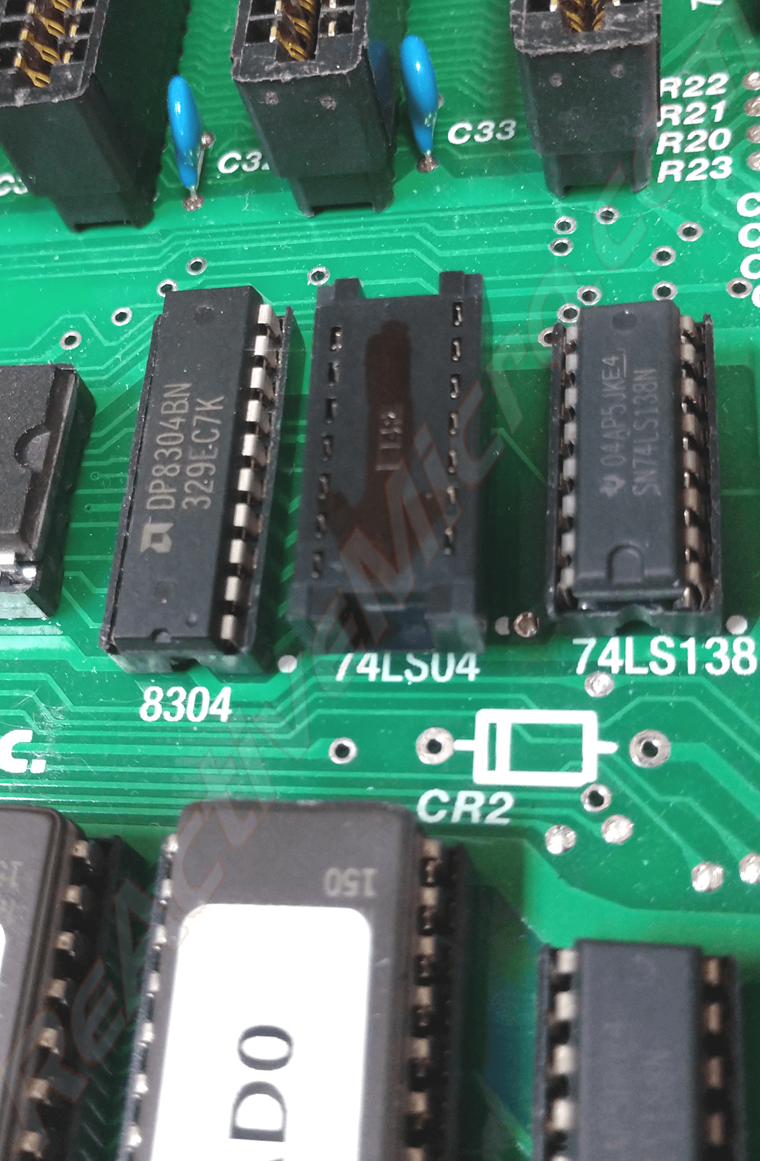
Description of issue: The motherboard won't beep. Displays rolling blocks on the screen. Removal of F13 produces the issue.
Location: F13, 74LS138, or sometimes a partly defective H10, or 8304.
Project Differences: 93-Series/27-Series
The Apple II plus Rev 7 RFI project from ReActiveMicro comes is two different variations, the 93-Series and the 27-Series boards.
Both motherboards operate exactly the same in all aspects, and are an exact clone of the original from Apple. The only difference is which family of system ROMs are natively supported on the board. The two options are the original 93-Series, and the later and more common 27-Series.
The concept for the 93-Series project is allowing users to retire their existing Apple II, II plus board and rely on the new motherboard board for a modern, rock solid replacement while maintaining that original look and feel. Users only need to swap their existing system ROMs and install the new board. It’s much simpler and less time consuming than a rebuild or to hunt for issues with an original 40 year old board that was built on a budget and not with longevity in mind. In contrast, the high quality parts and sockets used on the new motherboard will last at least another 40 years without issues. No more worry about intermittent issues from month to month. As noted, this version of the project DOES NOT COME with any system ROMs, users are required to swap their existing system ROMs.
The concept for the 27-Series project has all the same benefits listed for the 93-Series project, however this version of the project comes with system ROMs preinstalled. These ROMs are the more common 27-series ICs currently available. This also allows users a more simple option for firmware development and installing other ROMs found online.
ROM Differences (Technical): 93-Series/27-Series
"93" and 27" refer to the family or technology of a ROM IC. The 93-series ROMs were introduced in the early 70's, whereas the 27-Series ROMs were introduced in the late 70's. A lot had changed during this time in the industry.
The original Apple II and II plus use 9316 ROMs which have 2k storage each. These were 'masked' ROMs which were produced in a factory to Apple's specifications. At the time Apple started designing the II the 93-series ROMs were the only option available at a reasonable price. Later however the 27-series ROMs would be introduced which were less expensive and became the industry standard for several decades.
One of the enhancements of the Apple II plus was that it uses a 27-series ROM for its Character Generator since it was less expensive and the code stored was able to be customized at any time during production unlike a masked ROM. Apple however decided to keep the system ROMs in the II plus compatible with the original ROMs of the II and didn't change over to the 27-series. So 27-series ROMs will not work in an original II or II plus system, and an adapter would be needed.
ROMX and the 93-Series/27-Series Motherboards
The ROMX project is an add-on device that replaces the system ROM’s (D0-F8) and your Video ROM in your Apple II or II Plus computer. It stores up to 15 ROM images, and presents them for selection via an on-screen menu system on boot. In addition, the menu system itself (the ROMX firmware) and ROM images are updateable in-system.
The ROMX works as-is with the 93-series motherboards since they are a direct clone of Apple's design. So it installs and works the same exact way as the original Apple II or II Plus. The 27-series RM motherboard however utilitzes 27-series ROMs in place of the old 93-series System ROMs. This has the advantage to allowing 'standard' EPROMs to be used on the motherboard, but at the disadvantage of the ROMX not working as simply as on the 93-series boards.
The fix however is quite simple. The user of a 27-series board simply removes the 74LS04 at location H11 and installs a jumper between pins 8 and 9. The ROMX "27-series" version is sold with an easy to install DIP-14 Plug meant to replace the 74LS04 at location H11. This way users have the best of both worlds, the newer standard EPROMs and the ability to install and use the ROMX.
Here is a pic of the ROMX 27-Series DIP Plug adapter installed in H11. Notice the black on black arrow to denote Pin1 or the 'notch'. Install with arrow facing the keyboard end of the motherboard.
-
 ROMX 27-Series DIP Plug Adapter
The TheROMExchange did a write up on this mod as well here: https://theromexchange.com/blog/2nd-march-2021
Differences: Apple II Revision 0 and Apple II plus Rev 7 RFI
There are several key differences between the Apple II Revision 0 and Apple II plus Rev 7 RFI. Basically they are the same board, however the Rev 7 RFI has some key enhancements
- Power On Reset: The Rev 0 has no power on reset - the user must do it manually or have a Disk II Controller installed. The Rev 7 auto-resets itself on power up.
- ROMs: The Rev 0 came standard with Integer BASIC. The Rev 7 comes standard with Applesoft BASIC.
- RAM: The Rev 0 can use 4k and 16k DRAMs. The Rev 7 is 'hard set' to only use 16k DRAMs.
- Character Generator: The Rev 0 uses a 2513 ROM which is 5-bits. The Rev 7 uses a more common 27-series EPROM which is a full 8-bits.
- Video: The Rev 0 has several video issues which make them hard to use and limited 4 color palette for low and high-res. The Rev 7 fixed the video issues and expanded to color palette to 16 color low-res, and 6 color high-res.
- Timing: There were several timing issues that were fixed in the Rev 7 design.
- Power: The Rev 7 was enhanced with better power filtering to help prevent intermittent lockup issues reported in the Rev 0 design.
Notices
- Character Generator / Video ROM (location A5)
- The ROM on the Rev 7 RFI board is pinned for a 2716 EPROM. A 2732 also works as however the A11 address line is held 'high' on the motherboard, so only the 'top' half of the ROM is used. When programming a 2732 the firmware is loaded in to address 0800-0FFF.
- Also note worthy is the speed of the ROM used. Some ROMs with an access time of 350nS tend to cause artifacts on the screen when used. 300nS or better should be used. It has been getting harder to find 250-300nS speed grades for 2716 EPROMs, so 2732 ROMs are used to address this issue.
PAL and 50Hz Mod
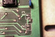
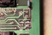
Apple designed the Apple II and II plus to be used with a PAL display as an option. A small mod is required, and can easily be undone if desired.
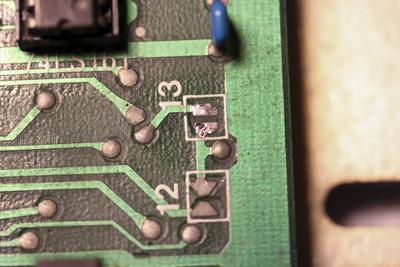
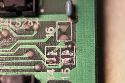
- Locate the following bow-ties of the mid-lower right side of motherboard: 12, 13, 14, 15, and 16. A "bow-tie" is a small, exposed trace, usually in a shape that resembles a formal dress black tie, that is designed to be soldered to make connection, or cut to break a connector. They are from an era before shunt jumpers. Bow-ties on the Rev 7 PCB all have small white boxes as an outline and a number close by to allow them to be more easily found and identified.
- Solder the pads together for 13, 14, and 15 bow-ties. And cut the trace between the arrows at bow-ties 12 and 16.
- Change out the crystal out at A1 to 14.25045MHz. Not all crystals are created equal, and you will need to find one with the correct ESR (about 25 ohms), load capacitance (series), and form factor (HC49).
- Done!
Note: Users may want to install square header pins and jumpers for the bow-ties. This would make changing setting a lot simpler in the future and is very inexpensive. Also, adding a socket designed for crystals or just a couple loose machined pins would be a good idea and is also inexpensive.
-
 Bow-ties on motherboard
 -
 Bow-tie 12-13
 -
 Bow-tie 14-16
 -
 Jumper idea
 -
 Crystal and socket


Credit: Thomas Gutmeier / 8-bit Home Computer Museum