Universal Enclosure PSU: Difference between revisions
(Created page with "340px|link=https://wiki.reactivemicro.com/images/b/b5/Title_Universal_PSU.svg Image:IMG 20201011 223519222 HDR-Wiki-tiny.png|thumb|U...") |
No edit summary |
||
| Line 3: | Line 3: | ||
The | The Universal PSU Enclosure is designed by [ReActiveMicro] to be an expensive PSU enclosure replacement and installed by the end user. | ||
As the name implies, the enclosure supports the Apple II, II Plus, //e, IIGS, and most clones. It was conceived, created, and designed by Henry of ReActiveMicro and released for sale to the Apple II Community on date. It's a simple to assemble, fun kit for anyone who needs a new PSU for system missing one, wants to retire their old PSU while keeping it original, or for a decent all-in-one bench supply. | |||
| Line 16: | Line 14: | ||
<strong>Sales:</strong> Visit the [https://store.reactivemicro.com/shop/ ReActiveMicro Store]. | <strong>Sales:</strong> Visit the [https://store.reactivemicro.com/shop/ ReActiveMicro Store]. | ||
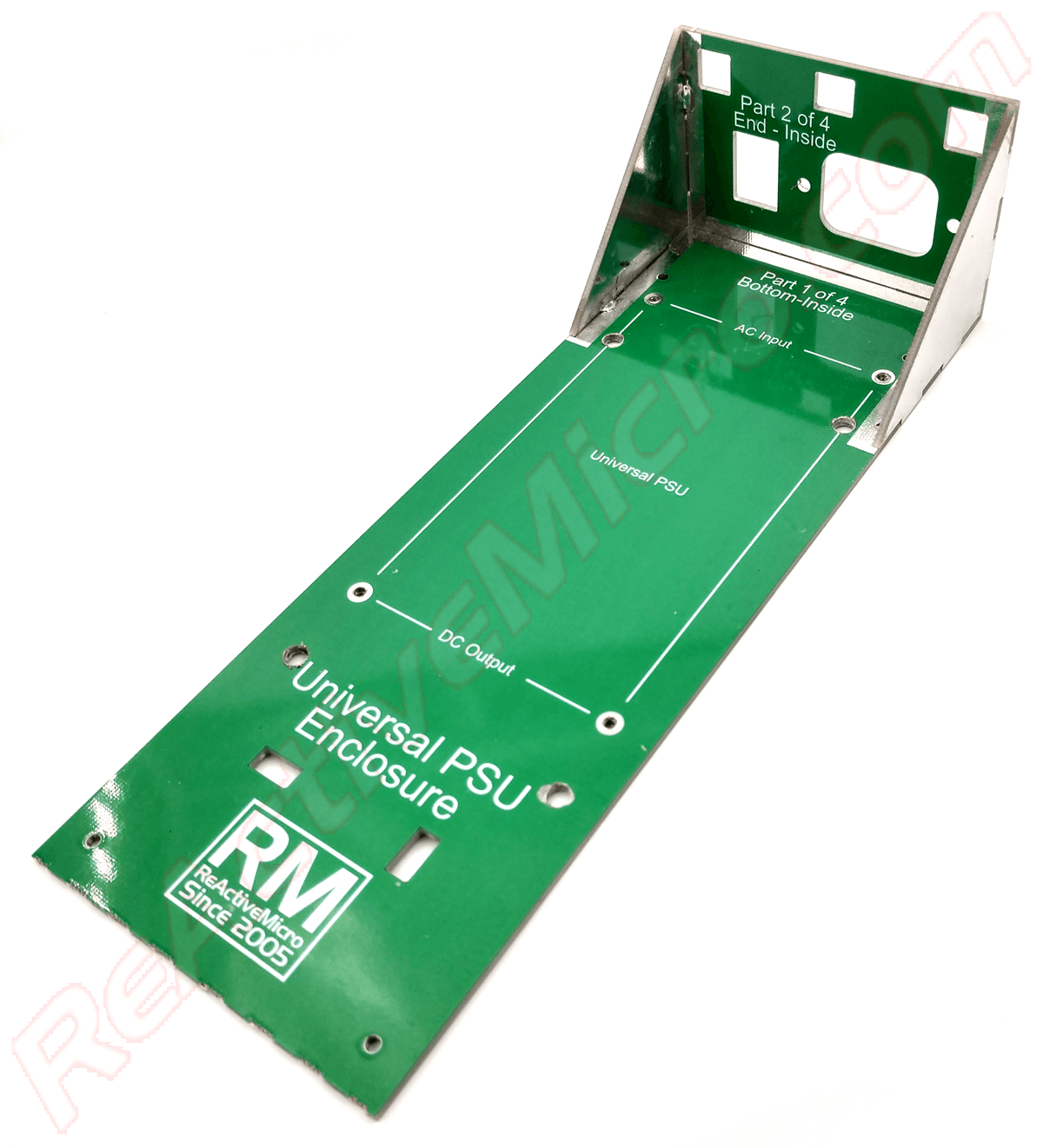
==Kit Assembly== | ==Kit Assembly== | ||
The kit comes as several panels which are soldered together. It's very simple and quick to assemble, like legos, and most users won't even need instructions. However with all our kits, we highly recommend at least skimming to quickly review. | |||
* Step 1: Assemble the bottom and the sides. Simplest way to start is to hold the end panel and side panel to the bottom panel. This will form a stable triangle which can easily be tacked in to place with some solder. One in place you can add a thicker and longer bead of solder to add strength. | |||
* Step 2: Add the remaining side. Solder all joints well and add plenty of solder. The whole seem doesn't need to be soldered, but ever 2" / 5cm is a good idea. And be sure to solder where the corners of the panels meet. | |||
Revision as of 12:59, 12 October 2020

The Universal PSU Enclosure is designed by [ReActiveMicro] to be an expensive PSU enclosure replacement and installed by the end user.
As the name implies, the enclosure supports the Apple II, II Plus, //e, IIGS, and most clones. It was conceived, created, and designed by Henry of ReActiveMicro and released for sale to the Apple II Community on date. It's a simple to assemble, fun kit for anyone who needs a new PSU for system missing one, wants to retire their old PSU while keeping it original, or for a decent all-in-one bench supply.
Product Status: Actively sold by ReActiveMicro.
Support: Post on the Discussion page (link above) or email ReActiveMicro Support.
Sales: Visit the ReActiveMicro Store.
Kit Assembly
The kit comes as several panels which are soldered together. It's very simple and quick to assemble, like legos, and most users won't even need instructions. However with all our kits, we highly recommend at least skimming to quickly review.
- Step 1: Assemble the bottom and the sides. Simplest way to start is to hold the end panel and side panel to the bottom panel. This will form a stable triangle which can easily be tacked in to place with some solder. One in place you can add a thicker and longer bead of solder to add strength.
- Step 2: Add the remaining side. Solder all joints well and add plenty of solder. The whole seem doesn't need to be soldered, but ever 2" / 5cm is a good idea. And be sure to solder where the corners of the panels meet.