A2FPGA: Difference between revisions
No edit summary |
(Added warning re: proper board orientation during installation.) |
||
| Line 30: | Line 30: | ||
IIgs ROM3 - Any Slot<br> | IIgs ROM3 - Any Slot<br> | ||
<br> | <br> | ||
<strong>WARNING! This board MUST be installed with the HDMI connector facing the forward keyboard end of the chassis! Failure to do so will result in damage to your Apple II as all bus lines are active.</strong> | |||
<strong>WARNING! | <br> | ||
<br> | |||
<b>NOTE:</b> | <b>NOTE:</b> | ||
*If Mockingboard is enabled, NO other card may be physically present in Slot 4. For IIgs, you must set the control panel slot 4 to "My Card" | *If Mockingboard is enabled, NO other card may be physically present in Slot 4. For IIgs, you must set the control panel slot 4 to "My Card" | ||
Revision as of 23:12, 17 April 2024

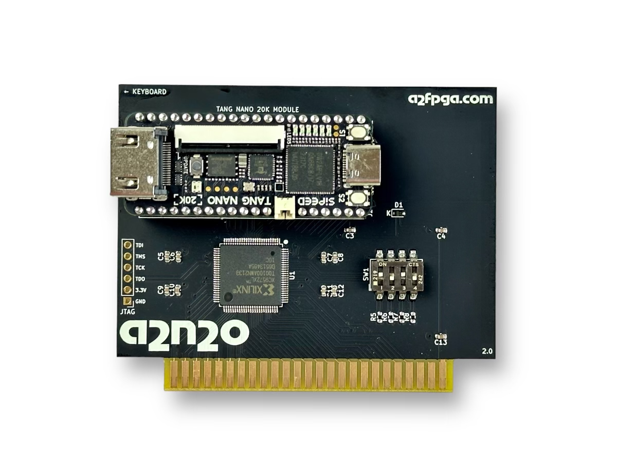
The A2FPGA is primarily an HD video and Mockingboard-compatible sound card for the Apple II, II+, //e, and IIgs. It's a small, Apple II peripheral card that can be installed in any Apple II slot (slot-7 recommended except for the IIgs ROM 0 or 1, which require slot 3) that uses a modern FPGA (field-programmable gate array or "programmable logic") to provide precise timing-accurate interfacing to the Apple II bus. This allows the card to capture all access to Apple II display memory in order to faithfully generate Apple text and graphics in crisp 720p 60Hz HD as well as providing the functionality of a number of popular peripheral cards in a single Apple II slot. The A2FPGA has been tested with Apple II, II+, //e, and IIgs models and brings the classic Apple II experience to a whole new level on any monitor or television.
Product Status: Actively sold by ReActiveMicro.
Support: Post on the Discussion page (link above) or email ReActiveMicro Support.
Sales: Visit the ReActiveMicro Store.
Features
As of April 2024 the standard features currently are:
720x480 @ 60Hz HDMI output supporting all Apple II, II+, //e, & IIgs display modes.
Mockingboard sound compatibility
Both Apple II system speaker audio AND Mockingboard audio are output to your HDMI display's speakers
Synetix SuperSprite and Ciarcia EZ-Color TMS9918a compatibility
Slots:
II/Plus/e - Any Slot, Recommended Slot 7
IIgs ROM0 - NOT TESTED, But Slot 3 ONLY
IIgs ROM1 - Slot 3 ONLY
IIgs ROM3 - Any Slot
WARNING! This board MUST be installed with the HDMI connector facing the forward keyboard end of the chassis! Failure to do so will result in damage to your Apple II as all bus lines are active.
NOTE:
- If Mockingboard is enabled, NO other card may be physically present in Slot 4. For IIgs, you must set the control panel slot 4 to "My Card"
- The FPGA used on A2FPGA takes ~2 seconds to power on and sync to an HDMI display. During this time the Apple II system is held in RESET, meaning the II will do nothing (not even beep) until the A2FPGA board has been fully setup and synched. The initial Apple II power on "beep" will be missed, but all subsequent Apple II sound can be output to HDMI if SW2 is ON.
DIP Switch Settings
The A2N20v2 has a 4-switch DIP switch that controls the following settings:
SW1: Enable Scanline effect when set to ON (default).
SW2: Enable Apple II speaker sounds via HDMI when set to ON (default).
SW3: Set to ON (default) for Power-on-Reset Hold - Delay Apple II start-up until FPGA is initialized and running.
SW4: Apple IIgs - Set to ON when installed in an Apple IIgs. OFF for II, II+ and II/e systems.
If Mockingboard functionality is enabled, no other card may be physically present in Slot 4 on any Apple II system. Further, if you have a IIgs, you must configure slot 4 as "My Card" in the Apple IIgs control panel.
Firmware / FPGA Core
The A2FPGA firmware is easily updated on any PC or Mac and is based on open-source code so that new functionality and bug fixes from the developer community can be added over time.
You can learn more about this exciting project on its public GitHub repository: https://github.com/a2fpga/a2fpga_core.
The team also maintains a presence on X (formerly Twitter) here: https://twitter.com/a2fpga.
UPDATING THE A2N20-V2 FPGA FIRMWARE
WINDOWS SYSTEMS
1. Download a2n20v2.fs as a raw download from GitHub (right-click and save). The location is here: https://raw.githubusercontent.com/a2fpga/a2fpga_core/main/boards/a2n20v2/impl/pnr/a2n20v2.fs
2. Install the Gowin programmer or the full GoWin IDE and tools by following this link in your browser: https://cdn.gowinsemi.com.cn/Gowin_V1.9.9Beta-4_Education_win.zip
3. Attach a USB cable from your PC to the Tang Nano 20K USB-C socket.
4. Launch the Gowin Programmer you installed in step 2. The Cable Setup dialog will appear and should detect the USB cable and the Tang Nano 20K device. The FPGA will appear in the device list as GW2AR-18C.
5. If any device appears in the device list with anything other than GW2AR-18C then click on it and hit the Delete Device button. If there are no devices showing after doing this, click Scan Device and it will say “Multi-device found”, select GW2AR-18C.
6. Right click on the device and select “Configure Device”
7. Select External Flash Mode, choose Generic Flash in External Flash Options, leave address at 0x000000. Select the a2n20v2.fs file in Programming Options File Name. Hit Save.
8. Hit Program/Configure. It will program the device.
9. Disconnect the USB cable and proceed with installing your A2FPGA into your Apple II.
MACOS AND LINUX SYSTEMS
 1. Install openfpgaloader. You can find it on GitHub here: https://github.com/trabucayre/openFPGALoader
 Instructions for installing on various platforms is located here: https://trabucayre.github.io/openFPGALoader/guide/install.html
 If you have a Mac, probably the easiest path is to use HomeBrew: brew install openfpgaloader
 If you have a Linux system, follow the instructions for installing openfpgaloader for your specific distribution located in the link above.
 If you want or need to build openfpgaloader by hand, the instructions for doing so are also available in the link above.
 2. Download a2n20v2.fs as a raw download from GitHub. (right-click and save the file)
 https://raw.githubusercontent.com/a2fpga/a2fpga_core/main/boards/a2n20v2/impl/pnr/a2n20v2.fs
 NOTE! Please remember this filename and the location where you saved it as you will need this for the next step!
 Alternatively, if you have git installed on your system, you can clone the repository locally and use the firmware located there.
 cd <YOUR_DIRECTORY>
 git clone https://github.com/a2fpga/a2fpga_core.git
 This will place a copy of the a2fpga_core repository into a subdirectory called a2fpga_core.
 3. Reprogram the Firmware of the Tang Nano 20K Module
 Connect either a USB-A to USB-C or USB-C to USB-C cable to your computer followed by connecting the other end (USB-C) to the Tang Nano 20K module that is mounted on the a2n20-V2 Multicard.
 You can now reprogram the firmware of your a2n20-V2 Multicard by issuing the following command:
 openfpgaloader -b tangnano20k -f <YOUR_DIRECTORY>/a2n20v2.fs
 Where <YOUR_DIRECTORY> is replaced by the directory name or fully qualified path where you saved the file in step 2.
 If you cloned the GitHub repository using git, the commands to reprogram your board are:
 cd <YOUR_DIRECTORY>
 openfpgaloader -b tangnano20k -f a2fpga_core/boards/a2n20v2/impl/pnr/a2n20v2.fs
 4. Staying Up To Date With New Firmware
 As new updates are made to the repository, you can either fetch a new copy of the file using the link supplied above, or you can update your local copy of the a2fpga_core repository from the latest version on GH using git pull:
 cd <DIR_CONTAINING_A2FPGA_CORE_FILES>
 git pull origin main
 From there, repeat the appropriate openfpgaloader command above after connecting your Tang Nano 20K module to your computer and your a2n20-V2 Multicard firmware will be reprogrammed.
Testing
The A2FPGA displays video immediately when installed in the correct slot. Sound depends on the DIP Switch setting.
Any diagnostic program can be used to test varying video modes. Other programs, such as games, could also be used. Sound testing can more simply be performed using the Mockingboard Demo disk.
For testing Synetix SuperSprite features, this link https://mirrors.apple2.org.za/ftp.apple.asimov.net/images/hardware/video/StarSprite-SuperSprite-Programs.zip is a ZIP file with images for the Synetix SuperSprite programs. When you unpack it, the Demonstration Disk is probably the best one to use for testing.
History
September 7th, 2023 A2FPGA contacted Henry to discuss their HDMI related project and about ReActiveMicro assisting with distribution and related sales, logistics, and support.