Apple II REV 0: Difference between revisions
No edit summary |
Mrtitanic777 (talk | contribs) ev. 0 Feplicas. |
||
| (8 intermediate revisions by 2 users not shown) | |||
| Line 1: | Line 1: | ||
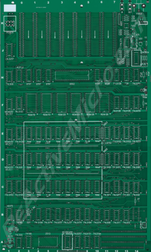
The Apple II REV 0 project was created by [http://www.willegal.net/appleii/appleii-recreation.htm Mike Willegal] in 2007 and the project was abandoned shortly after. In 2019 Logan Greer decided to continue the project and start to produce boards. On April 09,2019 Logan ordered 5 blank PCB boards from JLCPCB and also announced that he was selling them as blanks, | [[Image:2019-05-29_-_Rev_0_-_Wiki-tiny.png|thumb|Apple II Rev 0]] | ||
The Apple II REV 0 project was created by [http://www.willegal.net/appleii/appleii-recreation.htm Mike Willegal] in 2007 and the project was abandoned shortly after. In 2019 Logan Greer decided to continue the project and start to produce boards. On April 09,2019 Logan ordered 5 blank PCB boards from JLCPCB and also announced that he was selling them as blanks, and added options for a PCB with all the sockets soldered, or a completed hand assembled and tested board. | |||
Currently Logan is partnered with [[ReActiveMicro]] for sales and distribution, and Henry offers technical and project guidance | Currently Logan is no longer partnered with [[ReActiveMicro]] for sales and distribution, and Henry no longer offers technical and project guidance. | ||
<strong>Project Status:</strong> Completed. In production. Actively sold by ReActiveMicro. | <strong>Project Status:</strong> Completed. In production. Actively & only sold by ReActiveMicro. | ||
<strong>Support:</strong> Post on the [[{{TALKPAGENAME}}|Discussion]] page (link above) or email [https://www.reactivemicro.com/contact-us/ ReActiveMicro Support]. | <strong>Support:</strong> Post on the [[{{TALKPAGENAME}}|Discussion]] page (link above) or email [https://www.reactivemicro.com/contact-us/ ReActiveMicro Support]. | ||
<strong>Sales:</strong> Visit the [https://www.reactivemicro.com/shop/ ReActiveMicro Store]. | <strong>Sales:</strong> Visit the [https://www.reactivemicro.com/shop/ ReActiveMicro Store]. | ||
| Line 21: | Line 21: | ||
In early May Logan contacted Henry to discuss the project and ask for advise about parts, production, and having ReActiveMicro assist in selling the boards. | In early May Logan contacted Henry to discuss the project and ask for advise about parts, production, and having ReActiveMicro assist in selling the boards. | ||
As of 2020, Logan is no longer making nor selling Apple ll Rev. 0 Replicas. Logan has allowed Henry to continue selling boards. Logan no longer wants to be apart of this project. He has since been removed (per his request)... | |||
==Kit Assembly== | |||
If you purchased a Kit then the parts included as well as the PCB have basic labels. There are over 2000 pads which will need to be soldered. Those with intermediate knowledge should have little trouble assembling the kit from just these labels. The images of the motherboard can also be used for reference or determine orientation, such as transistors and diodes. | |||
<center>'''WE NEED PIC OF COMPLETED PCB HERE'''</center> | |||
Some care does need to be taken when installing capacitors and diodes however. | |||
If your kit includes Aluminum or Tantalum capacitors, or "caps" for short, then be sure to install them in the correct orientation. The PCB will be clearly marked with "+" signs for all cap locations when the orientation of the part matters, or a polarized part is normally used. Sometimes a non-polarized part is used in place of a polarized one and then its orientation does not matter. However install a polarized cap backwards and you will damage it. An Aluminum Electrolytic will have a strip pointing to the NEGATIVE end lead. A Tantalum Electrolytic will generally have a marking or stripe to denote (not always pointing to) the POSITIVE lead. | |||
All caps will have value markings on them. "106" is 10uF, and "104" is .1uF for example. 10uF is also physically a lot larger than .1uF. This should help identify the ceramic caps in the kit. They along with the Electrolytic caps can also clearly be seen in the assembled pic above. | |||
A diode also has a marking on it, and needs to be installed correctly as it only allows current to flow in one direction. Install it backwards and you won't usually damage it, however the circuit will no longer operate as intended. They can also clearly be seen in the assembled pic above. | |||
<center>'''WE NEED PIC OF COMPLETED PCB HERE'''</center> | |||
Your kit will include resistors. If so, they could be the less precise "4 band" style which are typically 5% tolerance. Or the more precise "4 band" style which are typically 1% tolerance. Here are some charts on how to read them to help make matching locations on your PCB more easy. On the II Rev 0 board the values of the resistors are also printed on the board. | |||
<gallery class="center" widths=400px heights=400px> | |||
File:4-band_Resistor.png|4-band Resistor Markings | |||
File:5-band_Resistor.jpg|5-band Resistor Markings | |||
</gallery> | |||
Latest revision as of 20:57, 20 June 2022

The Apple II REV 0 project was created by Mike Willegal in 2007 and the project was abandoned shortly after. In 2019 Logan Greer decided to continue the project and start to produce boards. On April 09,2019 Logan ordered 5 blank PCB boards from JLCPCB and also announced that he was selling them as blanks, and added options for a PCB with all the sockets soldered, or a completed hand assembled and tested board.
Currently Logan is no longer partnered with ReActiveMicro for sales and distribution, and Henry no longer offers technical and project guidance.
Project Status: Completed. In production. Actively & only sold by ReActiveMicro.
Support: Post on the Discussion page (link above) or email ReActiveMicro Support.
Sales: Visit the ReActiveMicro Store.
History
The Revival Of The Rev 0 Project. In late 2018 Logan discovered Mike Willegal's website and took interest in his Rev 0 project. He found the idea of reproducing the Rev 0 PCBs an interesting proposition. Interested in learning new things, Logan decided in early 2019 to order some PCBs with the intent to build a working unit and selling the extra boards to the Community. He announced his project in the Apple II Enthusiast's group on Facebook shortly after.
On April 09,2019 Logan ordered 5 blank PCB boards from JLCPCB. He also started to scavenge parts from a broken II+ he owned, and ordered the rest needed to complete an assembled a board.
By May Logan already sold a few blank boards.
In early May Logan contacted Henry to discuss the project and ask for advise about parts, production, and having ReActiveMicro assist in selling the boards.
As of 2020, Logan is no longer making nor selling Apple ll Rev. 0 Replicas. Logan has allowed Henry to continue selling boards. Logan no longer wants to be apart of this project. He has since been removed (per his request)...
Kit Assembly
If you purchased a Kit then the parts included as well as the PCB have basic labels. There are over 2000 pads which will need to be soldered. Those with intermediate knowledge should have little trouble assembling the kit from just these labels. The images of the motherboard can also be used for reference or determine orientation, such as transistors and diodes.
Some care does need to be taken when installing capacitors and diodes however.
If your kit includes Aluminum or Tantalum capacitors, or "caps" for short, then be sure to install them in the correct orientation. The PCB will be clearly marked with "+" signs for all cap locations when the orientation of the part matters, or a polarized part is normally used. Sometimes a non-polarized part is used in place of a polarized one and then its orientation does not matter. However install a polarized cap backwards and you will damage it. An Aluminum Electrolytic will have a strip pointing to the NEGATIVE end lead. A Tantalum Electrolytic will generally have a marking or stripe to denote (not always pointing to) the POSITIVE lead.
All caps will have value markings on them. "106" is 10uF, and "104" is .1uF for example. 10uF is also physically a lot larger than .1uF. This should help identify the ceramic caps in the kit. They along with the Electrolytic caps can also clearly be seen in the assembled pic above.
A diode also has a marking on it, and needs to be installed correctly as it only allows current to flow in one direction. Install it backwards and you won't usually damage it, however the circuit will no longer operate as intended. They can also clearly be seen in the assembled pic above.
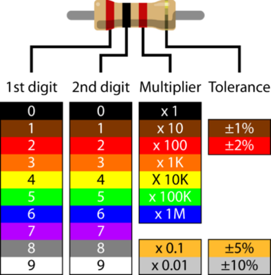
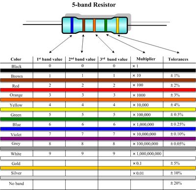
Your kit will include resistors. If so, they could be the less precise "4 band" style which are typically 5% tolerance. Or the more precise "4 band" style which are typically 1% tolerance. Here are some charts on how to read them to help make matching locations on your PCB more easy. On the II Rev 0 board the values of the resistors are also printed on the board.
-
4-band Resistor Markings
-
5-band Resistor Markings

