Universal Enclosure PSU: Difference between revisions
No edit summary |
|||
| (174 intermediate revisions by 6 users not shown) | |||
| Line 1: | Line 1: | ||
[[Image:Title_Universal_PSU.svg| | [[Image:Title_Universal_PSU.svg|700px|link=https://wiki.reactivemicro.com/images/b/b5/Title_Universal_PSU.svg]] | ||
[[Image:IMG_20201227_152312585_HDR-Wiki-tiny.png|thumb|Universal Enclosure PSU - v1.0.5 Proto|link=https://wiki.reactivemicro.com/images/c/ce/IMG_20201227_152312585_HDR-Wiki-tiny.png]] | |||
As the name implies, the enclosure supports the Apple II, II | The Universal Enclosure Power Supply Unit (PSU) is designed by [ReActiveMicro] to be an inexpensive PSU enclosure replacement and installed by the end user. | ||
As the name implies, the enclosure supports the Apple II, II ''plus'', //e, IIGS, and most clones. It was conceived, created, and designed by Henry of ReActiveMicro and released for sale to the Apple II Community on date. It's a simple to assemble, fun kit for anyone who needs a new PSU for system missing one, wants to retire their old PSU while keeping it original, or for a decent all-in-one bench supply. | |||
| Line 12: | Line 13: | ||
<strong>Support:</strong> Post on the [[{{TALKPAGENAME}}|Discussion]] page (link above) or email [https://store.reactivemicro.com/contact-us/ ReActiveMicro Support]. | <strong>Support:</strong> Post on the [[{{TALKPAGENAME}}|Discussion]] page (link above) or email [https://store.reactivemicro.com/contact-us/ ReActiveMicro Support]. | ||
<strong>Sales:</strong> Visit the [https://store.reactivemicro.com/shop/ ReActiveMicro Store]. | <strong>Sales:</strong> Visit the [https://store.reactivemicro.com/shop/ ReActiveMicro Store]. | ||
==Kit Assembly== | |||
'''Tools Required: Soldering Iron with Solder and Flux, Philips Screwdriver, Small Slotted Screwdriver, Wire Cutters/Strippers, Multimeter.''' | |||
The kit comes as several panels which are soldered together. It's very simple and quick to assemble, like legos, and most users won't even need instructions. However with all of our kits, we highly recommend at least skimming to quickly review. | |||
Below are pics of the panels and options. They show how you should lay them out and solder in place. The sides and ends are at a 90-degree to the bottom panel, however they are pictured flat for simplicity. Use these pics to reference your kit panels and how they should be installed. | |||
<gallery class="center" widths=450px heights=250px caption="Different Universal Enclosure PSU Panels for II, II ''plus'', //e, and IIGS> | |||
File:IMG_20210430_124656982-II-tiny.png|II/II ''plus'' and //e Enclosure Panel Locations|link=https://wiki.reactivemicro.com/images/a/a4/IMG_20210430_124656982-II-tiny.png | |||
File:IMG_20210430_124856726-IIgs-tiny.png|IIgs Enclosure Panel Locations|link=https://wiki.reactivemicro.com/images/3/37/IMG_20210430_124856726-IIgs-tiny.png | |||
</gallery> | |||
* Step 1: Find the bottom panel in the kit. Break the PCB if it will be installed in a II or II ''plus'', or as needed. | |||
* Step 2: Install the four M3 x 8mm brass standoffs on to the TOP side of the bottom panel. They will be soldered in to place. It's simplest to use the M3 Phillips screws to hold the standoffs in place then solder. Insert the screw from the BOTTOM of the panel, and install the standoff tightly on to the screw from the TOP side. Be sure to solder all around the standoff to the panel, and be sure to use flux when soldering. You can solder the standoffs in place without using the screws, but the screws help ensure the standoffs are centered and level with the panel. And issues with the placing of the standoffs could mean issues later when installed the Universal PSU. So take care to make sure the standoffs are fully seated to the panel and centered in place before soldering. When all four standoffs are soldered in place and have cooled down, remove the M3 screws. These screws are reused later to mount the Universal PSU. | |||
<gallery class="center" widths=350px heights=200px> | |||
File:IMG_20210430_143248637-Step1-tiny.png|Standoffs and M3 Screws|link=https://wiki.reactivemicro.com/images/8/85/IMG_20210430_143248637-Step1-tiny.png | |||
File:IMG_20210430_143629768-Step2-tiny.png|Standoff Screwed To Panel|link=https://wiki.reactivemicro.com/images/9/93/IMG_20210430_143629768-Step2-tiny.png | |||
File:IMG_20210430_143646250-Step3-tiny.png|M3 Screws Installed From Bottom|link=https://wiki.reactivemicro.com/images/2/2c/IMG_20210430_143646250-Step3-tiny.png | |||
File:IMG_20210430_144210770-Step4-tiny.png|Standoff Soldered To Bottom Panel|link=https://wiki.reactivemicro.com/images/d/d3/IMG_20210430_144210770-Step4-tiny.png | |||
</gallery> | |||
* Step 3: Assemble the bottom and the sides. Simplest way to start is to hold the end panel and side panel at 90-degrees to the bottom panel. This will form a stable triangle which can easily be tacked in to place with some solder. See example pic below, yellow circles are suggestions areas on where to start soldering to hold sides in place. We can also recommend using several rubber bands to hold all sides to allow for easy initial soldering. | |||
Note: If you purchased fan and meter options for your Universal Enclosure PSU then be sure to stall those sides correctly. See above for pics of which side to install meter panel. | |||
<gallery class="center" widths=450px heights=250px> | |||
<gallery class="center" widths=250px> | |||
File:IMG 20201012 131958279-Wiki-tiny.png|Solder Sided Together|link=https://wiki.reactivemicro.com/images/4/4b/IMG_20201012_131958279-Wiki-tiny.png | File:IMG 20201012 131958279-Wiki-tiny.png|Solder Sided Together|link=https://wiki.reactivemicro.com/images/4/4b/IMG_20201012_131958279-Wiki-tiny.png | ||
</gallery> | </gallery> | ||
* Step | * Step 4: Add the remaining side. Now you can solder all joints well and add plenty of solder. The whole seam doesn't need to be soldered, but 2" / 5cm is a good idea. And be sure to solder where the corners of the panels meet. A good solder seam is at least 1/2" / 1cm long. However you can solder the whole seam if you wish for added strength. | ||
* Step 5: Install C-14 and Switch in the end panel. Secure the C-14 with two screws and nuts. Then install the AC wires as pictured. Also install the AC wires to the C-14 and Switch. See the pic for correct wiring. Brown is "Live", Blue is "Common", Green is "Ground". | |||
Note: The C-14 is fit from the "inside", and the switch is fit from the "outside". | |||
<gallery class="center" widths=450px heights=250px> | |||
File:IMG 20201012 154842879 HDR-Wiki-tiny.png|C-14, Switch, And AC Wires|link=https://wiki.reactivemicro.com/images/e/ed/IMG_20201012_154842879_HDR-Wiki-tiny.png | |||
</gallery> | |||
* Step 6: Install the Universal PSU on to the standoffs inside the Universal Enclosure PSU using the four M3 pan head screws. Be sure to set the orange three position spring connector to the AC end with the AC wires. | |||
Note: Ground is supplied to the Apple system using the frame of the Apple II Enclosure and the mounting screws ensure this proper connection. Be sure to install ALL screws and make sure they are firmly tightened. | |||
* Step 7: Install the AC wires in to the Universal PSU. The brown wire is the HOT or the LIVE wire. The blue wire is Neutral. The green wire is Ground. | |||
Using a small slotted screwdriver, push the Brown wire into the orange three position spring connector in to the "L" connector. Its location is closest to the largest capacitor near the middle of the Universal PSU PCB. | |||
Next push the Green wire into the orange three position spring connector in to the "G" connector. Its '''middle''' location. | |||
Finally, push the Blue wire into the orange three position spring connector in to the "N" connector. Its location closest to the mounting screw in step 6. | |||
<gallery class="center" widths=450px heights=250px> | |||
File:P_20181105_155951_vHDR_Auto-Wiki-tiny.png|Orange Three Position Spring Connector - AC Input|link=https://wiki.reactivemicro.com/Universal_PSU_Kit#/media/File:P_20181105_155951_vHDR_Auto-Wiki-tiny.png | |||
</gallery> | |||
* Step 7: Install the standard DC Output Cable. Or see below for meter and fan connections. | |||
Note: Be sure to connect correctly. The two 'ramps' face each other. You can force the connector on backwards, so please be careful or damage will occur to your Apple system! If there are any doubts be sure to use a multimeter and verify the voltages are correctly output to the correct pins of the cable. This will be your ONLY chance to make sure things are correct before you destroy your motherboard. | |||
'''Done!''' | |||
==DC Output Cable - Meters and Fans== | |||
The Universal Enclosure PSU Kit comes with meter and fan options. Below is how to correctly wire in those options. | |||
<gallery class="center" widths=300px heights=140px caption="Fan and Meters Examples"> | |||
File:IMG_20201227_152312585_HDR-Wiki-tiny.png|IIgs Fan and Meters|link=https://wiki.reactivemicro.com/images/c/ce/IMG_20201227_152312585_HDR-Wiki-tiny.png | |||
File:IMG_20210606_165603696-IIe-wiki-tiny.png|IIe Meters|link=https://wiki.reactivemicro.com/images/7/73/IMG_20210606_165603696-IIe-wiki-tiny.png | |||
</gallery> | |||
===METERS Option: Same For IIe and IIgs=== | |||
* 1: First, install the meters into their locations. The large meter might need to be removed from it's housing, then the housing installed in to the side panel of the Universal Enclosure PSU from the outside. Then the meter installed into the housing from the inside. The smaller meters are installed from the inside, and need to be secured in place with small M2.3x5 screws. | |||
<gallery class="center" widths=300px heights=140px> | |||
File:IMG_20210430_183001877-Step1-tiny.png|Step 1: Remove Larger Meter From Housing|link=https://wiki.reactivemicro.com/images/0/00/IMG_20210430_183001877-Step1-tiny.png | |||
File:IMG_20210430_183221201-Step2-tiny.png|Step 2: Install Meter Housing Into Side Panel|link=https://wiki.reactivemicro.com/images/5/56/IMG_20210430_183221201-Step2-tiny.png | |||
File:IMG_20210430_183257680-Step3-tiny.png|Step 3 Inside: Install Meter Back In Housing|link=https://wiki.reactivemicro.com/images/4/4a/IMG_20210430_183257680-Step3-tiny.png | |||
File:IMG_20210430_183341129_HDR-Step3-tiny.png|Step 3 Outside: Install Meter Back In Housing|link=https://wiki.reactivemicro.com/images/5/53/IMG_20210430_183341129_HDR-Step3-tiny.png | |||
File:IMG_20210430_183424304-Step4-tiny.png|Step 4: Install Small Meters|link=https://wiki.reactivemicro.com/images/7/70/IMG_20210430_183424304-Step4-tiny.png | |||
File:IMG_20210430_183457302-Step5-tiny.png|Step 4: Screw Small Meter To Panel|link=https://wiki.reactivemicro.com/images/c/c8/IMG_20210430_183457302-Step5-tiny.png | |||
</gallery> | |||
* 2: Next is to wire the small meters to the PSU. Start by removing any connector or pins from the fan wires. Strip the wire and reinsert into the DC Output spring connector. To keep things simple, let's call the left side of the spring connector where we terminate a wire "Pin1", and the right side "Pin6". | |||
Note: You may want to tin the wires to make them simpler to deal with, or even twist several wire together and tin. | |||
<gallery class="center" widths=250px heights=250px> | |||
File:IMG_20210430_204057582_-12v-tiny.png|Step 1: -12v Meter, Black=Pin2, Red=Pin3 or Pin4|link=https://wiki.reactivemicro.com/images/8/84/IMG_20210430_204057582_-12v-tiny.png | |||
File:IMG_20210430_211547302_-5v-tiny.png|Step 2: -5v Meter, Black=Pin1, Red=Pin3 or Pin4|link=https://wiki.reactivemicro.com/images/f/fc/IMG_20210430_211547302_-5v-tiny.png | |||
File:IMG_20210430_212908561_+12v-tiny.png|Step 3: +12v Meter, Black=Pin3 or Pin4, Red=Pin6|link=https://wiki.reactivemicro.com/images/4/42/IMG_20210430_212908561_+12v-tiny.png | |||
</gallery> | |||
* 3: Finally, wire the large meter to the PSU. Start with the three wire connector. First, cut the tip off the thin black wire. This wire is not used. Next, insert both the thin red and yellow wires into Pin5. We are now done with the thin wires. | |||
<gallery class="center" widths=250px heights=250px> | |||
File:2021-05-02-PSU_Wiring_+5vMeter_ThinWires1-tiny.png|Insert Thin Red And Yellow Wires Into Pin5|link=https://wiki.reactivemicro.com/images/e/e5/2021-05-02-PSU_Wiring_+5vMeter_ThinWires1-tiny.png | |||
</gallery> | |||
Now go to the section below for your DC Output Cable wiring. | |||
<hr> | |||
===II, //e and IIGS DC Output Cables=== | |||
Next are the two thick wires on the meter connector. These wires are much thicker than the three wires in the last section. It might be simpler to remove the connector from the rear of the meter to work with the wires. | |||
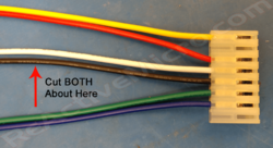
* 1: First take the DC Output Cable and cut the '''white''' and '''black''' wires about 2" (5cm) from the MTA-156 white connector which mates with the male DC Output connector of the PSU. DO NOT cut the white and black wires near the motherboard connector end of the DC Output cable. | |||
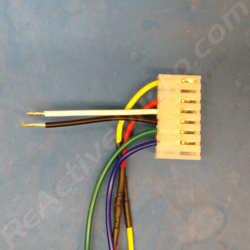
* 2: Strip all four the wires about 1/2" (1cm) to expose the inner wire. | |||
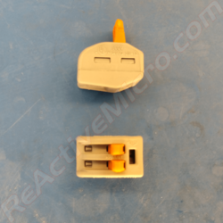
* 3: Now open the Wego wire splices (lever up) to get ready to splice the wires together with the meter's cable. It will take a good bit of force to open the levers. Don't worry about breaking anything. And no, they aren't stuck closed. It really takes a lot of force to pry the little lever up. They are a good grade of connector and bite in to the wires very well and securely. | |||
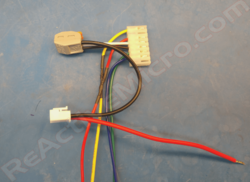
* 4: Lastly, insert the two white and black ground wires from the MTA-156 white connector of the DC Output Cable together in to one side/hole on the Wego splice connector and close the lever. This will lock both wire together in to the one splicing hole. Next, insert the black thick meter wire in to the Wego splice and close the lever. | |||
* 5: Repeat this same process with the other two white and black ground wires of the DC Output Cable and the red thick meter wire in to the Wego splice and close the lever. | |||
<gallery class="center" widths=250px heights=250px> | |||
File:IMG_20210502_154650118-Gounds1-tiny.png|Cut BOTH White and Black Ground Wires About 2" (5cm)|link=https://wiki.reactivemicro.com/images/5/58/IMG_20210502_154650118-Gounds1-tiny.png | |||
File:IMG_20210502_170639016-Grounds2-tiny.png|Strip Ground Wires|link=https://wiki.reactivemicro.com/images/0/04/IMG_20210502_170639016-Grounds2-tiny.png | |||
File:IMG 20210502 170749254-Grounds3-tiny.png|Open the Wego Splices|link=https://wiki.reactivemicro.com/images/8/85/IMG_20210502_170749254-Grounds3-tiny.png | |||
File:IMG_20210502_171015489-Grounds4-tiny.png|Splice MTA-156 White And Black Grounds To Meter Thick Black|link=https://wiki.reactivemicro.com/images/a/ac/IMG_20210502_171015489-Grounds4-tiny.png | |||
File:IMG_20210502_171139821-Grounds5-tiny.png|Splice The Remaining White And Black Grounds To Meter Thick Red|link=https://wiki.reactivemicro.com/images/8/80/IMG_20210502_171139821-Grounds5-tiny.png | |||
</gallery> | |||
* 6: When done splicing the wires, connect the 2 pin cable back to the rear of the larger meter, and the DC Output cable to the PSU. You can now connect the AC line plug and turn on the PSU for a test of the meters and fan. Be sure to check the DC Output connector to make sure the voltages are correct before connecting to your Apple II system. This is the last chance to make sure all is correct before you possibly damage your motherboard. | |||
Link to Apple IIe and IIGS motherboard pinouts: [https://apple2.org.za/gswv/a2zine/faqs/R023PINOUTS.htm https://apple2.org.za/gswv/a2zine/faqs/R023PINOUTS.htm] | |||
Done! | |||
<hr> | |||
===Universal DC Output Cable=== | |||
Next are the two thick wires on the meter connector. These wires are much thicker than the three wires in the last step. It might be simpler to remove the connector from the rear of the meter to work with the wires. | |||
* 1: First take the DC Output Cable and strip the '''white''' and '''black''' wires about 1/2" (1cm) to expose the inner wire. You'll notice two wires in the MTA-156 connector are already done for you. | |||
* 2: Now "open" the Wego wire splices (lever up) to get ready to splice the wires together with the meter's cable. It will take a good bit of force to open the levers. Don't worry about breaking anything. And no, they aren't stuck closed. It really takes a lot of force to pry the little lever up. They are a good grade of connector and bite in to the wires very well and securely. | |||
* 3: Lastly, insert the two white and black ground wires from the MTA-156 white connector of the DC Output Cable together in to one side/hole on the Wego splice connector and close the lever. This will lock both wire together in to the one splicing hole. Next, insert the black thick meter wire in to the Wego splice and close the lever. | |||
* 4: Repeat this same process with the other two white and black ground wires of the DC Output Cable and the red thick meter wire in to the Wego splice and close the lever. | |||
<gallery class="center" widths=250px heights=250px> | |||
File:IMG_20210502_170639016-Grounds2-tiny.png|Strip Ground Wires|link=https://wiki.reactivemicro.com/images/0/04/IMG_20210502_170639016-Grounds2-tiny.png | |||
File:IMG 20210502 170749254-Grounds3-tiny.png|Open the Wego Splices|link=https://wiki.reactivemicro.com/images/8/85/IMG_20210502_170749254-Grounds3-tiny.png | |||
File:IMG_20210502_171015489-Grounds4-tiny.png|Splice MTA-156 White And Black Grounds To Meter Thick Black|link=https://wiki.reactivemicro.com/images/a/ac/IMG_20210502_171015489-Grounds4-tiny.png | |||
File:IMG_20210502_171139821-Grounds5-tiny.png|Splice The Remaining White And Black Grounds To Meter Thick Red|link=https://wiki.reactivemicro.com/images/8/80/IMG_20210502_171139821-Grounds5-tiny.png | |||
</gallery> | |||
* 5: When done splicing the wires, connect the 2 pin cable back to the rear of the larger meter, and the DC Output cable to the PSU. You can now connect the AC line plug and turn on the PSU for a test of the meters and fan. Be sure to check the DC Output connector to make sure the voltages are correct before connecting to your Apple II system. This is the last chance to make sure all is correct before you possibly damage your motherboard. | |||
Link to Apple IIe and IIgs motherboard pinouts: [https://apple2.org.za/gswv/a2zine/faqs/R023PINOUTS.htm https://apple2.org.za/gswv/a2zine/faqs/R023PINOUTS.htm] | |||
Done! | |||
<hr> | |||
===IIGS FAN Option:=== | |||
* 1: First, install the fan's power in to the PSU spring connector. You can either cut the wires or remove the pins from their connector with a small screwdriver. Press on the metal tab to unlock the pin from the connector, then pull to remove. When unlocked it should slid out of the connector with only slight force. If not, then repress on the locking tab with more force and try to remove again. If you cut the wires then be sure to strip them to expose the metal core about 1/2" (12mm) then insert in to the DC Output spring connector. Press the top tab of the spring connector with a small screwdriver and a fair amount of force. Then insert the wire, and release the tab. The wire should now be locked in to the spring connector. If not then you may need to strip more wire and try again. See pic below for example connection. To keep things simple, let's call the left side of the spring connector where we terminate a wire "Pin1", and the right side "Pin6". | |||
* 2: Run the cable behind the heat-sink, against the PCB side. Leave most of the cable on the AC side of the Enclosure. The cable should be tucked between the heat-sink and PCB side so it doesn't prevent the fan from turning. | |||
* 3: Install the fan '''with the label facing up'''. It should fit snugly on to the mounting posts. Some pressure may be needed to fully seat the fan in to place. It's simpler to install by seating one side first, then when the fan is at an angle, start to seat the other side. See pic below for example. | |||
<gallery class="center" widths=250px heights=140px> | |||
File:IMG_20201227_153010320-Wiki-tiny.png|Step 1: Install Power, GND is Pin3 or Pin4, +12 is Pin6|link=https://wiki.reactivemicro.com/images/6/67/IMG_20201227_153010320-Wiki-tiny.png | |||
File:IMG_20201227_153052972_HDR-Wiki-tiny.png|Step 2: Tuck In Power Cable|link=https://wiki.reactivemicro.com/images/a/af/IMG_20201227_153052972_HDR-Wiki-tiny.png | |||
File:IMG_20201227_152401817-Wiki-tiny.png|Step 3: Install Fan, Label Side UP|link=https://wiki.reactivemicro.com/images/7/7b/IMG_20201227_152401817-Wiki-tiny.png | |||
</gallery> | |||
Done! | |||
Note: If you have the Meters option you can optionally install the black/ground of the fan in to the Black-White & Thick Red meter wire Wego connector to add the fan's power usage to the Amp Meter's display. | |||
<hr> | |||
===//e FANs Option:=== | |||
* 1: First, use the doubled sided tape to stick the two fans together to create a single 'unit'. Apply the tape to the middle flat area of the fan chassis. Then press the two fans together. They should looks as pictured on the bottom part of the pic. We recommend setting the power cables to the bottom left side, however they should be long enough to work in any orientation. The bottom side will help prevent them wires from hitting the fan once installed. But be sure the fans are facing the correct way as pictured so they air is venting OUTSIDE your case. | |||
* 2: Now install the fan unit inside your II ''plus'' or //e case on the left side, next to the PSU area. Take care to angle them enough so only little force is required to fit them in to place. They should just be small enough to fit, and once inside the vent area cavity they should have some room to move around. For best venting performance be sure to center them in the vent area and place close to the vents. No need to secure them in to place, but you can if desired although it can make future removal for cleaning more complex. They should just rest in this area without issue or noise, and is what we recommend. | |||
<gallery class="center" widths=250px heights=140px> | |||
File:IMG_20210603_214335231-IIe-fan-wiki-tiny.png|Step 1: Stick Fans Toegther|link=https://wiki.reactivemicro.com/images/3/3f/IMG_20210603_214335231-IIe-fan-wiki-tiny.png | |||
File:IMG_20210607_000501341-IIe-fan-wiki-tiny.png|Step 2: Angle Under PSU Vent Side|link=https://wiki.reactivemicro.com/images/a/ab/IMG_20210607_000501341-IIe-fan-wiki-tiny.png | |||
File:IMG_20210607_000540014-IIe-fan-wiki-tiny.png|Step 2: Slide In To Place And Center|link=https://wiki.reactivemicro.com/images/f/fe/IMG_20210607_000540014-IIe-fan-wiki-tiny.png | |||
</gallery> | |||
* 3: Next, install the Universal Enclosure PSU in to the IIe's case and screw in to place. Reuse your original PSU screws. You can also connect the DC Cable to the motherboard to help keep it out of the way. | |||
* 4: Finally, install the fan's power in to the PSU spring connector. You can either cut the wires or remove the pins from their connector with a small screwdriver. Press on the metal tab to unlock the pin from the connector, then pull to remove. When unlocked it should slid out of the connector with only slight force. If not, then repress on the locking tab with more force and try to remove again. If you cut the wires then be sure to strip them to expose the metal core about 1/2" (12mm) then insert in to the DC Output spring connector. Press the top tab of the spring connector with a small screwdriver and a fair amount of force. Then insert the wire, and release the tab. The wire should now be locked in to the spring connector. If not then you may need to strip more wire and try again. See pic below for example connection. To keep things simple, let's call the left side of the spring connector where we terminate a wire "Pin1", and the right side "Pin6". | |||
<gallery class="center" widths=250px heights=140px> | |||
File:IMG_20201227_153010320-Wiki-tiny.png|Step 1: Install Power, GND is Pin3 or Pin4, +12 is Pin6|link=https://wiki.reactivemicro.com/images/6/67/IMG_20201227_153010320-Wiki-tiny.png | |||
</gallery> | |||
Done! | |||
Note: If you have the Meters option you can optionally install the black/ground of the fans in to the Black-White & Thick Red meter wire Wego connector to add the fan's power usage to the Amp Meter's display. | |||
==Reviews With Assembly Instructions== | |||
A couple user pics of what the Universal Enclosure PSU with fans and meters looks like in their IIe clear case from [https://maceffects.com/ Mac Effects]. | |||
<gallery class="center" heights=200px widths=280px> | |||
File:2022-11-10_-_IMG_0552-wiki.jpg|Credit: Eric Sirinsky|link=https://wiki.reactivemicro.com/images/1/1e/2022-11-10_-_IMG_0552-wiki.jpg | |||
File:IMG_0550.jpg|Credit: Eric Sirinsky|link=https://wiki.reactivemicro.com/images/1/11/IMG_0550.jpg | |||
</gallery> | |||
{{#ev:youtube|GMcpk2Df5LM|400|right|Joe's Computer Museum: ReActiveMicro Universal Power Supply|frame}} | |||
On June 18th, 2021 Joe from Joe's Computer Museum posted a build video of the Universal Enclosure PSU Kit for the IIgs. He shows how simple and fun this kit can be, as well as a finished product. A good vid to review before building your kit! | |||
<br> | |||
<br> | |||
<br> | |||
<br> | |||
<br> | |||
<br> | |||
<br> | |||
<br> | |||
<br> | |||
<br> | |||
<br> | |||
<br> | |||
{{#ev:youtube|TbE7UpX1x44|400|right|Chris Torrence: ReActiveMicro's New Power Supply Kit|frame}} | |||
On June 18th, 2021 Chris Torrence posted a build video of the Universal Enclosure PSU Kit for the II/e. He shows how simple and fun this kit can be, as well as a finished product. A good vid to review before building your kit! | |||
<br> | |||
<br> | |||
<br> | |||
<br> | |||
<br> | |||
<br> | |||
<br> | |||
<br> | |||
<br> | |||
<br> | |||
<br> | |||
<br> | |||
==History== | ==History== | ||
When Henry created the [Universal PSU Kit] in 2015 he also started research in to what it would take to create a custom enclosure. The initial concept was going to be a full clone of what Apple Computer produced. However any metal enclosure about $1k or more for single proto units, and at least $85 per unit in quantities under 250 units. These prices meant either | When Henry created the [[Universal PSU Kit]] in 2015 he also started research in to what it would take to create a custom enclosure. The initial concept was going to be a full clone of what Apple Computer had produced. However any metal enclosure would be about $1k or more for single proto units, and at least $85 per unit in quantities under 250 units. These prices meant either metalwork had to come down in price, or some other material would be needed. | ||
Henry then started to look in to 3D printing in conductive composites and even metalized plastic. Although these did mostly work, the price was still very expensive and the metal coating in most cases wasn't very durable. Several hobbyist in the retro Community contacted Henry to possibly offer help, however all these offers ended in the same thing being learned - working in metal is very expensive. So Henry would need to find other options. | |||
In 2018 Ultimate Apple 2 (UA2) completed their own project called the Ultimate Enclosure. It was fully metal, and in the style of Apple Computers it consisted of a case and a lid. [https://www.reactivemicro.com/2018/10/05/new-store-items-ultimate-universal-power-supply-universal-dc-output-cable/ The retail price was $95 and released on October 5, 2018.] During this time Henry had been busy with other projects and didn't want to compete with UA2, especially with their added risk with a large investment due to the cost of metal work. Stock of enclosures was however single/closed source and not always available, Also the current design left some room for improvement. So Henry continued with research and ideas. Assuming UA2 doesn't do anything more with the design perhaps it will be viable to continue with the planned project. | |||
Several ideas and materials were tested. Meters, fans, and kit ideas were all researched. In July 2020 an old CAD design was revised and a new proto completed and ordered. The new material allowed such low cost production costs and versatility that the project could be ordered factory assembled or in kits for end users to assemble. The cost was also a 10th or less of metal, and unlike metal it allowed for parts to all be produced flat which would save in space with stock and shipping. | |||
Once the initial proto was assembled it was clear this concept was viable and allowed for simple changes and features to be added in the future with little or no costs for tooling, unlike metal. Meters and fans were added shortly after, and custom DC Output Cable designs were worked out to keep costs low and to allow maximum flexibility for the end user | |||
==Versions== | ==Versions== | ||
In 2015 research in to what it would take to create a custom enclosure. Several PSUs were evaluated and several well versed Community members consulted as to their input. We decided to use a 'long' IIgs PSU which would allow for IIe and IIgs usage with no changes. However this PSU was too long to fit in the II and II | In 2015 research in to what it would take to create a custom enclosure. Several PSUs were evaluated and several well versed Community members consulted as to their input. We decided to use a 'long' IIgs PSU which would allow for IIe and IIgs usage with no changes. However this PSU was too long to fit in the II and II ''plus'' due to the placement of the speaker. In an attempt to produce only one version of the enclosure a modification would be needed to allow the user shorten the enclosure at will. Two main options seemed possible. One being a removable bracket, and the other being a way to snap off the enclosure. The issue with a snap off solution would be possible sharp edged and a risk of getting injured. | ||
The initial designs started in 2017. Several companies and Community members provided CAD and ideas for a simple yet versatile layout. | The initial designs started in 2017. Several companies and Community members provided CAD and ideas for a simple yet versatile layout. | ||
| Line 66: | Line 280: | ||
</gallery> | </gallery> | ||
The next design was also the last with metal in mind. This version also incorporated a user breakable end to allow the enclosure to fit in a II and II | The next design was also the last with metal in mind. This version also incorporated a user breakable end to allow the enclosure to fit in a II and II ''plus'' case. Although the concept works, it's a share edge and some care is needed when making the bend. | ||
<gallery class="center" widths=250px caption="Design by: Manila Gear"> | <gallery class="center" widths=250px caption="Design by: Manila Gear"> | ||
File:2017-12-17 - ReActicveMicro - PSU Enclossure- Design2 - 3-Wiki-tiny.png|Last 3D CAD Concept|link=https://wiki.reactivemicro.com/images/e/e7/2017-12-17_-_ReActicveMicro_-_PSU_Enclossure-_Design2_-_3-Wiki-tiny.png | File:2017-12-17 - ReActicveMicro - PSU Enclossure- Design2 - 3-Wiki-tiny.png|Last 3D CAD Concept|link=https://wiki.reactivemicro.com/images/e/e7/2017-12-17_-_ReActicveMicro_-_PSU_Enclossure-_Design2_-_3-Wiki-tiny.png | ||
| Line 77: | Line 291: | ||
While research, fitting, and refinement was going on Ultimate Apple 2 (UA2) released their "Ultimate Enclosure" in mid-2018. So our main development stopped for a while to help judge the market and actual demand, to receive some actual end user feedback, and help make sure UA2 was successful in recouping their initial investment. The most common comment we received was about the amount of cost, followed by being impressed by the quality. So it seemed we were on the right path for an enclosure project. | While research, fitting, and refinement was going on Ultimate Apple 2 (UA2) released their "Ultimate Enclosure" in mid-2018. So our main development stopped for a while to help judge the market and actual demand, to receive some actual end user feedback, and help make sure UA2 was successful in recouping their initial investment. The most common comment we received was about the amount of cost, followed by being impressed by the quality. So it seemed we were on the right path for an enclosure project. | ||
In 2020 stock for the Ultimate Enclosure started to become erratic due to the COVID pandemic mixed with the complexity of the design. At this point there had been several runs produced and the design didn't really change. So it seemed a good time to look back in to the Universal PSU | In 2020 stock for the Ultimate Enclosure started to become erratic due to the COVID pandemic mixed with the complexity of the design. At this point there had been several runs produced and the design didn't really change. So it seemed a good time to look back in to the Universal Enclosure PSU as it had become officially now named and not only offer a less expensive solution, but also one with many more options such as fans for active cooling and meters for those looking to know there PSU's output or to help measure a peripheral's draw. | ||
New designs were produced which were low cost, allowed for many options, strong, and conductive. The new design also allowed for kits to be produced which would also help lower retail pricing as well as improved bulk ordering. This new version also help prove the project as being possible to produce and some ideas about costs. Now options could be looked in to. | New designs were produced which were low cost, allowed for many options, strong, and conductive. The new design also allowed for kits to be produced which would also help lower retail pricing as well as improved bulk ordering. This new version also help prove the project as being possible to produce and some ideas about costs. Now options could be looked in to. | ||
<gallery class="center" widths=250px caption="Universal PSU | <gallery class="center" widths=250px caption="Universal Enclosure PSU - Proto v1.0.2"> | ||
File:IMG 20201011 223519222 HDR-Wiki-tiny.png|Unit Missing | File:IMG 20201011 223519222 HDR-Wiki-tiny.png|Unit Missing IIGS 'Tail' - Used for II and //e Tests|link=https://wiki.reactivemicro.com/images/6/64/IMG_20201011_223519222_HDR-Wiki-tiny.png | ||
</gallery> | </gallery> | ||
The next proto revision came with new, longer sides to help with stability in the | The next proto revision came with new, longer sides to help with stability in the IIGS. It also was the first time fans and meters were being testing in-system. Now final touches could be added to the design, a firm BOM worked out, and production pricing start to be quoted. Sample units were sent to a few beta users to help create the Wiki page as well as for feedback about assembly of the kits. | ||
<gallery class="center" widths=250px caption="Universal PSU | <gallery class="center" widths=250px caption="Universal Enclosure PSU - Proto v1.0.3"> | ||
File:IMG 20201012 125032696 HDR-Wiki-tiny.png| | File:IMG 20201012 125032696 HDR-Wiki-tiny.png|IIGS Version with Meters And Fans|link=https://wiki.reactivemicro.com/images/b/b1/IMG_20201012_125032696_HDR-Wiki-tiny.png | ||
File:IMG 20201012 125045322 HDR-Wiki-tiny.png| | File:IMG 20201012 125045322 HDR-Wiki-tiny.png|IIGS Version 'End'||link=https://wiki.reactivemicro.com/images/1/1a/IMG_20201012_125045322_HDR-Wiki-tiny.png | ||
File:IMG 20200925 200802313-Wiki-tiny.png|Testing Of Meters. +5v Amp Meter Working Well.|link=https://wiki.reactivemicro.com/images/9/90/IMG_20200925_200802313-Wiki-tiny.png | File:IMG 20200925 200802313-Wiki-tiny.png|Testing Of Meters. +5v Amp Meter Working Well.|link=https://wiki.reactivemicro.com/images/9/90/IMG_20200925_200802313-Wiki-tiny.png | ||
</gallery> | </gallery> | ||
Latest revision as of 21:57, 10 November 2022
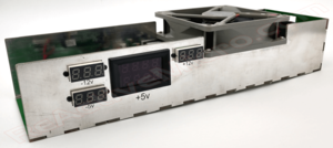
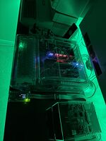
The Universal Enclosure Power Supply Unit (PSU) is designed by [ReActiveMicro] to be an inexpensive PSU enclosure replacement and installed by the end user.
As the name implies, the enclosure supports the Apple II, II plus, //e, IIGS, and most clones. It was conceived, created, and designed by Henry of ReActiveMicro and released for sale to the Apple II Community on date. It's a simple to assemble, fun kit for anyone who needs a new PSU for system missing one, wants to retire their old PSU while keeping it original, or for a decent all-in-one bench supply.
Product Status: Actively sold by ReActiveMicro.
Support: Post on the Discussion page (link above) or email ReActiveMicro Support.
Sales: Visit the ReActiveMicro Store.
Kit Assembly
Tools Required: Soldering Iron with Solder and Flux, Philips Screwdriver, Small Slotted Screwdriver, Wire Cutters/Strippers, Multimeter.
The kit comes as several panels which are soldered together. It's very simple and quick to assemble, like legos, and most users won't even need instructions. However with all of our kits, we highly recommend at least skimming to quickly review.
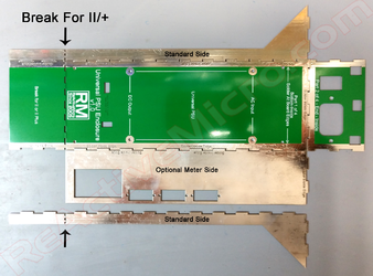
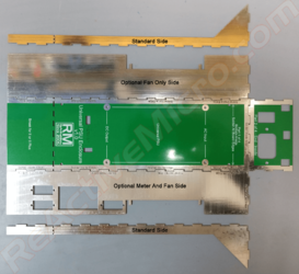
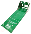
Below are pics of the panels and options. They show how you should lay them out and solder in place. The sides and ends are at a 90-degree to the bottom panel, however they are pictured flat for simplicity. Use these pics to reference your kit panels and how they should be installed.
- Different Universal Enclosure PSU Panels for II, II plus, //e, and IIGS
-
II/II plus and //e Enclosure Panel Locations
-
IIgs Enclosure Panel Locations
- Step 1: Find the bottom panel in the kit. Break the PCB if it will be installed in a II or II plus, or as needed.
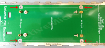
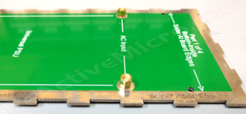
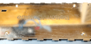
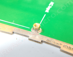
- Step 2: Install the four M3 x 8mm brass standoffs on to the TOP side of the bottom panel. They will be soldered in to place. It's simplest to use the M3 Phillips screws to hold the standoffs in place then solder. Insert the screw from the BOTTOM of the panel, and install the standoff tightly on to the screw from the TOP side. Be sure to solder all around the standoff to the panel, and be sure to use flux when soldering. You can solder the standoffs in place without using the screws, but the screws help ensure the standoffs are centered and level with the panel. And issues with the placing of the standoffs could mean issues later when installed the Universal PSU. So take care to make sure the standoffs are fully seated to the panel and centered in place before soldering. When all four standoffs are soldered in place and have cooled down, remove the M3 screws. These screws are reused later to mount the Universal PSU.
-
Standoffs and M3 Screws
-
Standoff Screwed To Panel
-
M3 Screws Installed From Bottom
-
Standoff Soldered To Bottom Panel
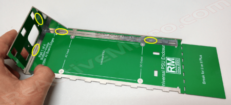
- Step 3: Assemble the bottom and the sides. Simplest way to start is to hold the end panel and side panel at 90-degrees to the bottom panel. This will form a stable triangle which can easily be tacked in to place with some solder. See example pic below, yellow circles are suggestions areas on where to start soldering to hold sides in place. We can also recommend using several rubber bands to hold all sides to allow for easy initial soldering.
Note: If you purchased fan and meter options for your Universal Enclosure PSU then be sure to stall those sides correctly. See above for pics of which side to install meter panel.
-
Solder Sided Together
- Step 4: Add the remaining side. Now you can solder all joints well and add plenty of solder. The whole seam doesn't need to be soldered, but 2" / 5cm is a good idea. And be sure to solder where the corners of the panels meet. A good solder seam is at least 1/2" / 1cm long. However you can solder the whole seam if you wish for added strength.
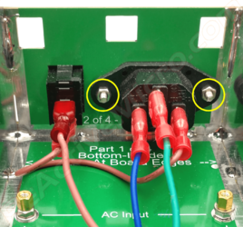
- Step 5: Install C-14 and Switch in the end panel. Secure the C-14 with two screws and nuts. Then install the AC wires as pictured. Also install the AC wires to the C-14 and Switch. See the pic for correct wiring. Brown is "Live", Blue is "Common", Green is "Ground".
Note: The C-14 is fit from the "inside", and the switch is fit from the "outside".
-
C-14, Switch, And AC Wires
- Step 6: Install the Universal PSU on to the standoffs inside the Universal Enclosure PSU using the four M3 pan head screws. Be sure to set the orange three position spring connector to the AC end with the AC wires.
Note: Ground is supplied to the Apple system using the frame of the Apple II Enclosure and the mounting screws ensure this proper connection. Be sure to install ALL screws and make sure they are firmly tightened.
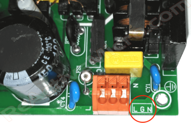
- Step 7: Install the AC wires in to the Universal PSU. The brown wire is the HOT or the LIVE wire. The blue wire is Neutral. The green wire is Ground.
Using a small slotted screwdriver, push the Brown wire into the orange three position spring connector in to the "L" connector. Its location is closest to the largest capacitor near the middle of the Universal PSU PCB. Next push the Green wire into the orange three position spring connector in to the "G" connector. Its middle location. Finally, push the Blue wire into the orange three position spring connector in to the "N" connector. Its location closest to the mounting screw in step 6.
-
Orange Three Position Spring Connector - AC Input
- Step 7: Install the standard DC Output Cable. Or see below for meter and fan connections.
Note: Be sure to connect correctly. The two 'ramps' face each other. You can force the connector on backwards, so please be careful or damage will occur to your Apple system! If there are any doubts be sure to use a multimeter and verify the voltages are correctly output to the correct pins of the cable. This will be your ONLY chance to make sure things are correct before you destroy your motherboard.
Done!
DC Output Cable - Meters and Fans
The Universal Enclosure PSU Kit comes with meter and fan options. Below is how to correctly wire in those options.
- Fan and Meters Examples
-
IIgs Fan and Meters
-
IIe Meters
METERS Option: Same For IIe and IIgs
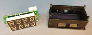
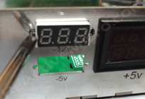
- 1: First, install the meters into their locations. The large meter might need to be removed from it's housing, then the housing installed in to the side panel of the Universal Enclosure PSU from the outside. Then the meter installed into the housing from the inside. The smaller meters are installed from the inside, and need to be secured in place with small M2.3x5 screws.
-
Step 1: Remove Larger Meter From Housing
-
Step 2: Install Meter Housing Into Side Panel
-
Step 3 Inside: Install Meter Back In Housing
-
Step 3 Outside: Install Meter Back In Housing
-
Step 4: Install Small Meters
-
Step 4: Screw Small Meter To Panel
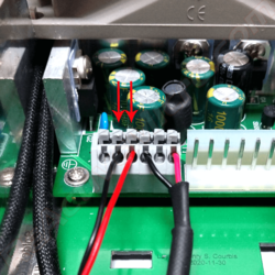
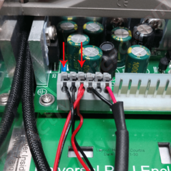
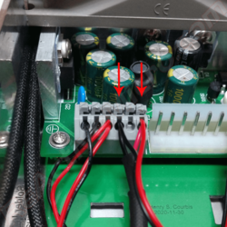
- 2: Next is to wire the small meters to the PSU. Start by removing any connector or pins from the fan wires. Strip the wire and reinsert into the DC Output spring connector. To keep things simple, let's call the left side of the spring connector where we terminate a wire "Pin1", and the right side "Pin6".
Note: You may want to tin the wires to make them simpler to deal with, or even twist several wire together and tin.
-
Step 1: -12v Meter, Black=Pin2, Red=Pin3 or Pin4
-
Step 2: -5v Meter, Black=Pin1, Red=Pin3 or Pin4
-
Step 3: +12v Meter, Black=Pin3 or Pin4, Red=Pin6
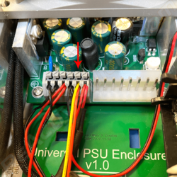
- 3: Finally, wire the large meter to the PSU. Start with the three wire connector. First, cut the tip off the thin black wire. This wire is not used. Next, insert both the thin red and yellow wires into Pin5. We are now done with the thin wires.
-
Insert Thin Red And Yellow Wires Into Pin5
Now go to the section below for your DC Output Cable wiring.
II, //e and IIGS DC Output Cables
Next are the two thick wires on the meter connector. These wires are much thicker than the three wires in the last section. It might be simpler to remove the connector from the rear of the meter to work with the wires.
- 1: First take the DC Output Cable and cut the white and black wires about 2" (5cm) from the MTA-156 white connector which mates with the male DC Output connector of the PSU. DO NOT cut the white and black wires near the motherboard connector end of the DC Output cable.
- 2: Strip all four the wires about 1/2" (1cm) to expose the inner wire.
- 3: Now open the Wego wire splices (lever up) to get ready to splice the wires together with the meter's cable. It will take a good bit of force to open the levers. Don't worry about breaking anything. And no, they aren't stuck closed. It really takes a lot of force to pry the little lever up. They are a good grade of connector and bite in to the wires very well and securely.
- 4: Lastly, insert the two white and black ground wires from the MTA-156 white connector of the DC Output Cable together in to one side/hole on the Wego splice connector and close the lever. This will lock both wire together in to the one splicing hole. Next, insert the black thick meter wire in to the Wego splice and close the lever.
- 5: Repeat this same process with the other two white and black ground wires of the DC Output Cable and the red thick meter wire in to the Wego splice and close the lever.
-
Cut BOTH White and Black Ground Wires About 2" (5cm)
-
Strip Ground Wires
-
Open the Wego Splices
-
Splice MTA-156 White And Black Grounds To Meter Thick Black
-
Splice The Remaining White And Black Grounds To Meter Thick Red
- 6: When done splicing the wires, connect the 2 pin cable back to the rear of the larger meter, and the DC Output cable to the PSU. You can now connect the AC line plug and turn on the PSU for a test of the meters and fan. Be sure to check the DC Output connector to make sure the voltages are correct before connecting to your Apple II system. This is the last chance to make sure all is correct before you possibly damage your motherboard.
Link to Apple IIe and IIGS motherboard pinouts: https://apple2.org.za/gswv/a2zine/faqs/R023PINOUTS.htm
Done!
Universal DC Output Cable
Next are the two thick wires on the meter connector. These wires are much thicker than the three wires in the last step. It might be simpler to remove the connector from the rear of the meter to work with the wires.
- 1: First take the DC Output Cable and strip the white and black wires about 1/2" (1cm) to expose the inner wire. You'll notice two wires in the MTA-156 connector are already done for you.
- 2: Now "open" the Wego wire splices (lever up) to get ready to splice the wires together with the meter's cable. It will take a good bit of force to open the levers. Don't worry about breaking anything. And no, they aren't stuck closed. It really takes a lot of force to pry the little lever up. They are a good grade of connector and bite in to the wires very well and securely.
- 3: Lastly, insert the two white and black ground wires from the MTA-156 white connector of the DC Output Cable together in to one side/hole on the Wego splice connector and close the lever. This will lock both wire together in to the one splicing hole. Next, insert the black thick meter wire in to the Wego splice and close the lever.
- 4: Repeat this same process with the other two white and black ground wires of the DC Output Cable and the red thick meter wire in to the Wego splice and close the lever.
-
Strip Ground Wires
-
Open the Wego Splices
-
Splice MTA-156 White And Black Grounds To Meter Thick Black
-
Splice The Remaining White And Black Grounds To Meter Thick Red
- 5: When done splicing the wires, connect the 2 pin cable back to the rear of the larger meter, and the DC Output cable to the PSU. You can now connect the AC line plug and turn on the PSU for a test of the meters and fan. Be sure to check the DC Output connector to make sure the voltages are correct before connecting to your Apple II system. This is the last chance to make sure all is correct before you possibly damage your motherboard.
Link to Apple IIe and IIgs motherboard pinouts: https://apple2.org.za/gswv/a2zine/faqs/R023PINOUTS.htm
Done!
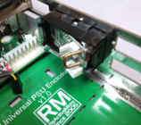
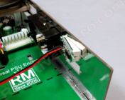
IIGS FAN Option:
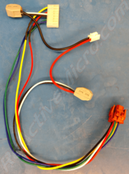
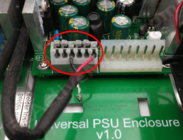
- 1: First, install the fan's power in to the PSU spring connector. You can either cut the wires or remove the pins from their connector with a small screwdriver. Press on the metal tab to unlock the pin from the connector, then pull to remove. When unlocked it should slid out of the connector with only slight force. If not, then repress on the locking tab with more force and try to remove again. If you cut the wires then be sure to strip them to expose the metal core about 1/2" (12mm) then insert in to the DC Output spring connector. Press the top tab of the spring connector with a small screwdriver and a fair amount of force. Then insert the wire, and release the tab. The wire should now be locked in to the spring connector. If not then you may need to strip more wire and try again. See pic below for example connection. To keep things simple, let's call the left side of the spring connector where we terminate a wire "Pin1", and the right side "Pin6".
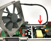
- 2: Run the cable behind the heat-sink, against the PCB side. Leave most of the cable on the AC side of the Enclosure. The cable should be tucked between the heat-sink and PCB side so it doesn't prevent the fan from turning.
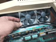
- 3: Install the fan with the label facing up. It should fit snugly on to the mounting posts. Some pressure may be needed to fully seat the fan in to place. It's simpler to install by seating one side first, then when the fan is at an angle, start to seat the other side. See pic below for example.
-
Step 1: Install Power, GND is Pin3 or Pin4, +12 is Pin6
-
Step 2: Tuck In Power Cable
-
Step 3: Install Fan, Label Side UP
Done!
Note: If you have the Meters option you can optionally install the black/ground of the fan in to the Black-White & Thick Red meter wire Wego connector to add the fan's power usage to the Amp Meter's display.
//e FANs Option:
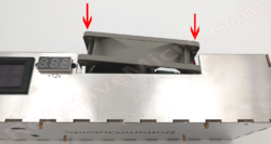
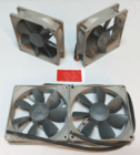
- 1: First, use the doubled sided tape to stick the two fans together to create a single 'unit'. Apply the tape to the middle flat area of the fan chassis. Then press the two fans together. They should looks as pictured on the bottom part of the pic. We recommend setting the power cables to the bottom left side, however they should be long enough to work in any orientation. The bottom side will help prevent them wires from hitting the fan once installed. But be sure the fans are facing the correct way as pictured so they air is venting OUTSIDE your case.
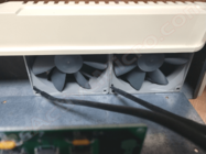
- 2: Now install the fan unit inside your II plus or //e case on the left side, next to the PSU area. Take care to angle them enough so only little force is required to fit them in to place. They should just be small enough to fit, and once inside the vent area cavity they should have some room to move around. For best venting performance be sure to center them in the vent area and place close to the vents. No need to secure them in to place, but you can if desired although it can make future removal for cleaning more complex. They should just rest in this area without issue or noise, and is what we recommend.
-
Step 1: Stick Fans Toegther
-
Step 2: Angle Under PSU Vent Side
-
Step 2: Slide In To Place And Center
- 3: Next, install the Universal Enclosure PSU in to the IIe's case and screw in to place. Reuse your original PSU screws. You can also connect the DC Cable to the motherboard to help keep it out of the way.
- 4: Finally, install the fan's power in to the PSU spring connector. You can either cut the wires or remove the pins from their connector with a small screwdriver. Press on the metal tab to unlock the pin from the connector, then pull to remove. When unlocked it should slid out of the connector with only slight force. If not, then repress on the locking tab with more force and try to remove again. If you cut the wires then be sure to strip them to expose the metal core about 1/2" (12mm) then insert in to the DC Output spring connector. Press the top tab of the spring connector with a small screwdriver and a fair amount of force. Then insert the wire, and release the tab. The wire should now be locked in to the spring connector. If not then you may need to strip more wire and try again. See pic below for example connection. To keep things simple, let's call the left side of the spring connector where we terminate a wire "Pin1", and the right side "Pin6".
-
Step 1: Install Power, GND is Pin3 or Pin4, +12 is Pin6
Done!
Note: If you have the Meters option you can optionally install the black/ground of the fans in to the Black-White & Thick Red meter wire Wego connector to add the fan's power usage to the Amp Meter's display.
Reviews With Assembly Instructions
A couple user pics of what the Universal Enclosure PSU with fans and meters looks like in their IIe clear case from Mac Effects.
-
Credit: Eric Sirinsky
-
Credit: Eric Sirinsky
On June 18th, 2021 Joe from Joe's Computer Museum posted a build video of the Universal Enclosure PSU Kit for the IIgs. He shows how simple and fun this kit can be, as well as a finished product. A good vid to review before building your kit!
On June 18th, 2021 Chris Torrence posted a build video of the Universal Enclosure PSU Kit for the II/e. He shows how simple and fun this kit can be, as well as a finished product. A good vid to review before building your kit!
History
When Henry created the Universal PSU Kit in 2015 he also started research in to what it would take to create a custom enclosure. The initial concept was going to be a full clone of what Apple Computer had produced. However any metal enclosure would be about $1k or more for single proto units, and at least $85 per unit in quantities under 250 units. These prices meant either metalwork had to come down in price, or some other material would be needed.
Henry then started to look in to 3D printing in conductive composites and even metalized plastic. Although these did mostly work, the price was still very expensive and the metal coating in most cases wasn't very durable. Several hobbyist in the retro Community contacted Henry to possibly offer help, however all these offers ended in the same thing being learned - working in metal is very expensive. So Henry would need to find other options.
In 2018 Ultimate Apple 2 (UA2) completed their own project called the Ultimate Enclosure. It was fully metal, and in the style of Apple Computers it consisted of a case and a lid. The retail price was $95 and released on October 5, 2018. During this time Henry had been busy with other projects and didn't want to compete with UA2, especially with their added risk with a large investment due to the cost of metal work. Stock of enclosures was however single/closed source and not always available, Also the current design left some room for improvement. So Henry continued with research and ideas. Assuming UA2 doesn't do anything more with the design perhaps it will be viable to continue with the planned project.
Several ideas and materials were tested. Meters, fans, and kit ideas were all researched. In July 2020 an old CAD design was revised and a new proto completed and ordered. The new material allowed such low cost production costs and versatility that the project could be ordered factory assembled or in kits for end users to assemble. The cost was also a 10th or less of metal, and unlike metal it allowed for parts to all be produced flat which would save in space with stock and shipping.
Once the initial proto was assembled it was clear this concept was viable and allowed for simple changes and features to be added in the future with little or no costs for tooling, unlike metal. Meters and fans were added shortly after, and custom DC Output Cable designs were worked out to keep costs low and to allow maximum flexibility for the end user
Versions
In 2015 research in to what it would take to create a custom enclosure. Several PSUs were evaluated and several well versed Community members consulted as to their input. We decided to use a 'long' IIgs PSU which would allow for IIe and IIgs usage with no changes. However this PSU was too long to fit in the II and II plus due to the placement of the speaker. In an attempt to produce only one version of the enclosure a modification would be needed to allow the user shorten the enclosure at will. Two main options seemed possible. One being a removable bracket, and the other being a way to snap off the enclosure. The issue with a snap off solution would be possible sharp edged and a risk of getting injured.
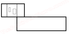
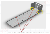
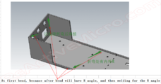
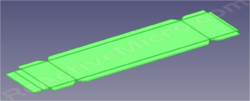
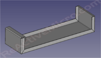
The initial designs started in 2017. Several companies and Community members provided CAD and ideas for a simple yet versatile layout.
- Design by: Abesttec Metal Technology
-
Initial MS-Paint Concept
-
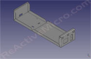
Initial 3D CAD Concept
-
Initial 3D CAD Concept
-
Breakoff End Idea
This initial concept touched on some key points. First, in order for the design to be low cost it would not come with a cover standard. Possibly it would be an option, but the costs for just a simple cover was over $20 each. A cover isn't functional or useful for anything except to keep heat in or hands out. Since it's almost impossible to be shocked by our Universal PSU once it's mounted we didn't see much use for a cover even from a safety standpoint. And next thing we knew we needed for this design would be some kind of side feature to help add some rigidity to the long piece of metal. We also strived to keep the design in one sheet and as simple as possible to keep the costs to a minimun.
The following design tried to improve the strength things as well as improve safety with edge bends. So no more sharp edges, but with added costs and complexity.
- Design by: Abesttec Metal Technology
-
Improved 3D CAD Concept
-
Improved 3D CAD Concept
-
Improved 3D CAD Concept
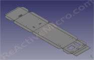
The next design was also the last with metal in mind. This version also incorporated a user breakable end to allow the enclosure to fit in a II and II plus case. Although the concept works, it's a share edge and some care is needed when making the bend.
- Design by: Manila Gear
-
Last 3D CAD Concept
-
Last 3D CAD Concept
-
Last 3D CAD Concept
A lot was learned with these protos. The main issue with these designs in metal is there's no 'simple' way to change or fix anything, to allow for options such as fans or meters. All new revisions would take weeks to create and cost hundreds or even thousands of dollars to produce only a few samples. The metal concept and design was forged by Apple Computers, with it's main feature being strength, followed by its conductivity. Perhaps there are other, more modern materials which could better fit our needs and be simpler to work with and at a lower cost.
While research, fitting, and refinement was going on Ultimate Apple 2 (UA2) released their "Ultimate Enclosure" in mid-2018. So our main development stopped for a while to help judge the market and actual demand, to receive some actual end user feedback, and help make sure UA2 was successful in recouping their initial investment. The most common comment we received was about the amount of cost, followed by being impressed by the quality. So it seemed we were on the right path for an enclosure project.
In 2020 stock for the Ultimate Enclosure started to become erratic due to the COVID pandemic mixed with the complexity of the design. At this point there had been several runs produced and the design didn't really change. So it seemed a good time to look back in to the Universal Enclosure PSU as it had become officially now named and not only offer a less expensive solution, but also one with many more options such as fans for active cooling and meters for those looking to know there PSU's output or to help measure a peripheral's draw.
New designs were produced which were low cost, allowed for many options, strong, and conductive. The new design also allowed for kits to be produced which would also help lower retail pricing as well as improved bulk ordering. This new version also help prove the project as being possible to produce and some ideas about costs. Now options could be looked in to.
- Universal Enclosure PSU - Proto v1.0.2
-
Unit Missing IIGS 'Tail' - Used for II and //e Tests
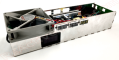
The next proto revision came with new, longer sides to help with stability in the IIGS. It also was the first time fans and meters were being testing in-system. Now final touches could be added to the design, a firm BOM worked out, and production pricing start to be quoted. Sample units were sent to a few beta users to help create the Wiki page as well as for feedback about assembly of the kits.
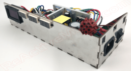
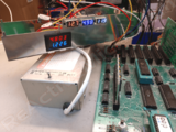
- Universal Enclosure PSU - Proto v1.0.3
-
IIGS Version with Meters And Fans
-
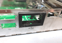
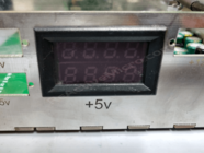
Testing Of Meters. +5v Amp Meter Working Well.

